A pulley bone extension device

A technology of extension device and pulley, which is applied in medical science, surgery, etc., can solve the problems of unable to control the extension length, prolong the treatment time of patients, poor reliability and controllability, etc., so as to facilitate the problem of excessive extension, shorten the treatment time, Applicable effect

Active Publication Date: 2020-12-18
盐城市湛安智感科技有限公司
View PDF14 Cites 0 Cited by
  • Summary
  • Abstract
  • Description
  • Claims
  • Application Information

AI Technical Summary

Problems solved by technology

However, when the device is adjusted, the extension length cannot be constantly controlled, and the extension length has great randomness. Once the extension length is too long or too short, it will increase the callus formation time, thereby prolonging the patient's treatment time. The efficiency is low and reliable. less controllable

Method used


Image

  • A pulley bone extension device
  • A pulley bone extension device
  • A pulley bone extension device

Examples


specific Embodiment approach 1

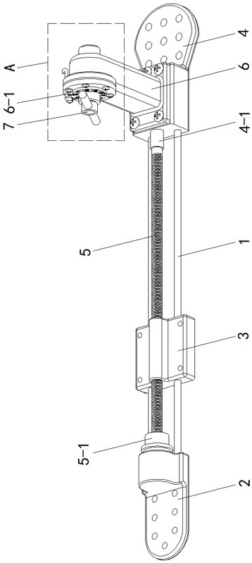
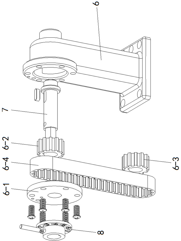
[0015] Specific implementation mode one: as Figure 1~Figure 6 As shown, the present invention discloses a belt pulley bone extension device, which includes a fixed osseointegration part 2, a movable osseointegrated part 3, a fixed osseointegrated part 2 4, a lead screw 5, a pulley drive box 6, a hand-held rotary rod 7 and two A guide rod 1, the two guide rods 1 are arranged side by side and are fixedly installed between the fixed osseointegration part 1 and the fixed osseointegration part 2 4, and the movable osseointegration part 3 is slidably installed on the two guide rods 1 , the screw 5 is axially arranged between the two guide rods 1, and one end of the screw 5 is inserted into the preset shaft hole at the connecting end of the fixed bone joint-2 through a thrust ball bearing 5-1, and is movable. The osseointegration part 3 is provided with a screw hole matched with the lead screw 5 and threadedly connected with the lead screw 5. The shape of the connection end of the f...

specific Embodiment approach 2

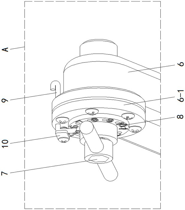
[0016] Specific implementation mode two: as figure 2 , 5 As shown in . The flanges 6-1 can be locked by a locking device.

specific Embodiment approach 3

[0017] Specific implementation mode three: as Figure 5 , 6 As shown, this embodiment is a further description of the second specific embodiment. The locking device includes a positioning pin 9 and a locking pressure piece 10. Jack 8-1, the outer surface of the flange 6-1 is provided with a plurality of positioning blind holes in one-to-one correspondence with the plurality of positioning jacks 8-1, and the positioning pin 9 is slidably inserted into the flange 6-1 In the pin through hole set at the edge position, one end of the positioning pin 9 is reversely bent to have a plug joint, and any positioning socket 8-1 can be inserted and positioned with the positioning blind hole corresponding to the flange 6-1, The locking pressing piece 10 is installed on the flange 6-1 through locking screws and can compress the positioning pin 9.


PUM


Abstract

The invention provides a novel bone lengthening device adopting a belt pulley, and relates to a medical apparatus for the orthopedics department. Two guide rods are fixed between a fixed bone connector I and a fixed bone connector II, a movable bone connector slides on the two guide rods, one end of a lead screw is inserted in an axial hole of the connecting end of the fixed bone connector I through a thrust ball bearing, the movable bone connector is in threaded connection with the lead screw, the connecting rod of the fixed bone connector II is rectangular-groove-shaped and is provided witha shaft sleeve in a communicating manner along the axial direction, the other end of the lead screw rotatably extends into the fixed bone connector II through the shaft sleeve, the bottom end of a belt pulley drive box is arranged to be open and is fixed to the groove opening of the fixed bone connector II, a flange plate is fixed to the top end of the belt pulley drive box, a hand-holding rotating rod is rotatably mounted in a center hole of the flange plate, an upper transmission wheel is fixed to the inner end of the hand-holding rotating rod, a lower transmission wheel is fixed to the other end of the lead screw, and a transmission belt sleeves between the lower transmission wheel and the upper transmission wheel. The traction lengthening for the skeleton can be carried out at any time, the treatment time is shortened, and the pain of patients is alleviated.

Description

technical field [0001] The invention relates to an orthopedic medical device, in particular to a pulley bone extension device. Background technique [0002] Bone lengthening is currently an effective method to treat limb shortening deformity and restore or improve limb function. Among them, callus extension of metaphysis of long tubular bone is a common osteotomy extension method with large extension length, fast bone healing, less injury, relatively few complications, and simple operation. It means that the periosteum is reserved behind the metaphyseal bone, and the mesenchymal cells in the periosteum with strong osteogenic ability will heal the bone through the formation of callus. At this time, a slow and continuous traction force is applied through the bone extension device, which can make the The callus formed at the osteotomy is slowly extended to achieve the purpose of bone lengthening. [0003] The current bone extension devices generally use external fixation meth...

Claims


Application Information

Patent Timeline
Patent Type & Authority Patents(China)
IPC IPC(8): A61B17/56
CPCA61B17/56A61B2017/564
Inventor 刘济源刘学广周日同周求湛刘萍萍王俊
Owner 盐城市湛安智感科技有限公司
Why Eureka
Try Eureka