A sheave extension device
A bone extension and sheave technology, applied in the field of sheave bone extension devices, can solve the problems of inability to constantly control the length of extension, poor reliability and controllability, and increase the time for callus formation, so as to achieve the problem of excessive extension and applicability Strong, shortening effect of treatment time
- Summary
- Abstract
- Description
- Claims
- Application Information
AI Technical Summary
Problems solved by technology
Method used
Image
Examples
specific Embodiment approach 1
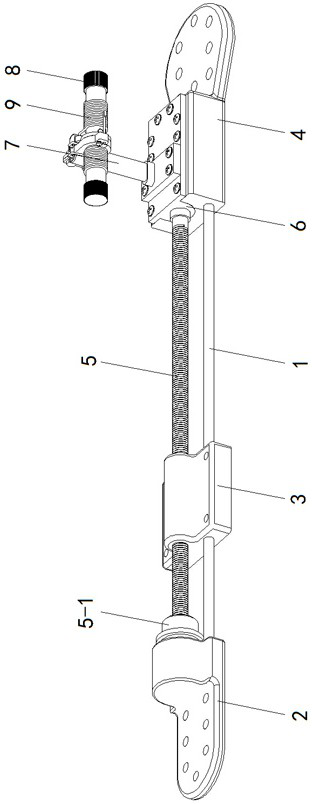
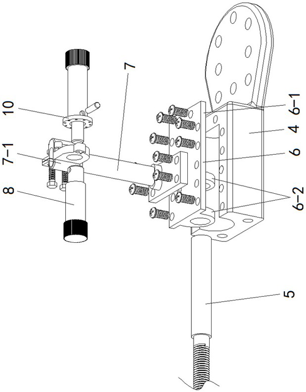
[0015] Specific implementation mode one: as Figure 1~Figure 6 As shown, the present invention discloses a sheave bone extension device, which includes a fixed osseointegration part 1, a movable osseointegrated part 3, a fixed osseointegrated part 24, a lead screw 5, a cover plate bushing 6, and a sheave drive frame And two guide rods 1, the two guide rods 1 are arranged side by side and fixedly installed between the fixed bone joint part 1 and the fixed bone joint part 2 4, and the movable bone joint part 3 is slidably installed on the two guide rods 1, the lead screw 5 is arranged axially between the two guide rods 1, and one end of the lead screw 5 is inserted into the shaft hole preset at the corresponding position of the fixed osseointegration part 1 through a thrust ball bearing 5-1 , the movable osseointegration part 3 is provided with a screw hole matched with the lead screw 5 and threadedly connected with the lead screw 5, and the outer surface of the fixed osseointeg...
specific Embodiment approach 2
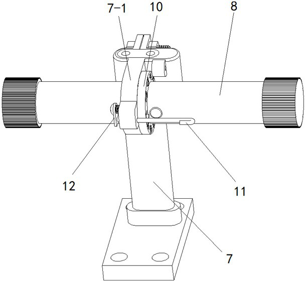
[0016] Specific implementation mode two: as figure 2 , 3 As shown, this embodiment is a further description of Embodiment 1. The sheave drive frame includes a rope drum 7, a hand-rotated rope rod 8 and two steel wire ropes 9. The bottom end of the rope drum 7 and the cover plate portion 6-1 is fixedly connected, and the top of the rope drum 7 is fixedly installed with a rope rod shaft seat 7-1, and the middle position of the hand-rotated rope rod 8 is rotationally connected with the rope rod shaft seat 7-1, and the two steel wire ropes 9 One end is respectively fixed and tightly wound on both sides of the hand-rotating rope rod 8, and the other ends of the two steel wire ropes 9 are penetrated into the cover plate part 6-1 through the rope drum 7, and are respectively fixed and tightly wound on the other end of the lead screw 5. Corresponding position.
specific Embodiment approach 3
[0017] Specific implementation mode three: as Figure 5 As shown, this embodiment is a further description of the second specific embodiment. The two steel wire ropes 9 are respectively wound in spring-like directions on both sides. The winding direction is the same.
PUM
 Abstract
Description
Claims
Application Information
 - R&D
- Intellectual Property
- Life Sciences
- Materials
- Tech Scout
- Unparalleled Data Quality
- Higher Quality Content
- 60% Fewer Hallucinations
Browse by: Latest US Patents, China's latest patents, Technical Efficacy Thesaurus, Application Domain, Technology Topic, Popular Technical Reports.
© 2025 PatSnap. All rights reserved.Legal|Privacy policy|Modern Slavery Act Transparency Statement|Sitemap|About US| Contact US: help@patsnap.com


