
Traffic lighting system based on weather changes

A technology of lighting system and weather change, applied in the arrangement of variable traffic instructions, lighting devices, lighting auxiliary devices, etc., can solve problems such as rear-end collisions, single response methods, and traffic accidents, and achieve accident prevention, simple structure, and reliable work Sexual Ascension Effects

Inactive Publication Date: 2020-08-07
余颖
View PDF0 Cites 0 Cited by
  • Summary
  • Abstract
  • Description
  • Claims
  • Application Information

AI Technical Summary

Problems solved by technology

[0002] Changes in the weather often involve some heavy snow, heavy rain, hail and other weather, as well as some infrequent heavy fog and foggy weather. During this process, motor vehicles and pedestrians cannot clearly see the road conditions ahead when they are moving normally on the road. Some traffic accidents are prone to occur. What is more dangerous in the process is the fog on the expressway. It is not uncommon for multiple vehicles to carry out continuous rear-end collisions. This makes the life safety of personnel unable to be guaranteed. The way to deal with these bad weather is too simple, and some identification cards with signs and need light source to reflect are often used to remind drivers and pedestrians, which makes the existing traffic lighting equipment unable to efficiently guide and remind people and vehicles , so that the working efficiency of the equipment cannot be guaranteed, and it will also increase the risk factor of personnel and drivers, and increase the risk of vehicles and pedestrians

Method used


Image

  • Traffic lighting system based on weather changes
  • Traffic lighting system based on weather changes
  • Traffic lighting system based on weather changes

Examples


Embodiment Construction

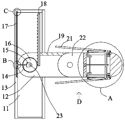
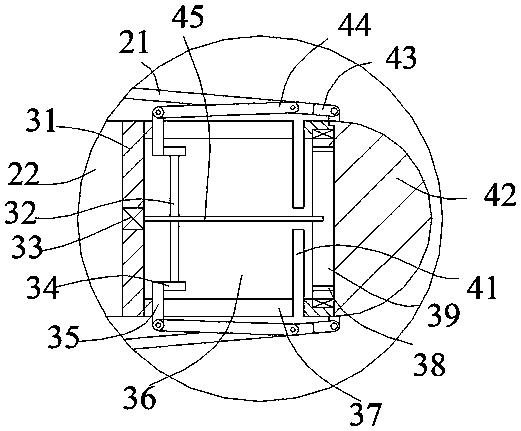
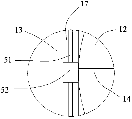
[0026] Such as Figure 1-Figure 8 As shown, the present invention is described in detail. For the convenience of description, the orientations mentioned below are now stipulated as follows: figure 1The up, down, left, right, front and back directions of the projection relationship are consistent. A traffic lighting system based on weather changes in the present invention includes a housing 13, and an open inner cavity 11 is arranged in the inner cavity 11, and the inner cavity 11 slides A rotating handle 19 is provided, and an open cavity 12 is arranged inside the rotating handle 19, and a side rotating plate 22 is arranged on the outer side of the rotating handle 19, and one side of the side rotating plate 22 is fixed. There is a middle fixed box 31, the middle fixed box 31 is provided with an open middle matching inner cavity 36, and the end wall of the middle matching inner cavity 36 is connected with a semi-circular annular opening 41, and the inner cavity 11 and the inner...


PUM


Abstract

The invention discloses a traffic lighting system based on weather changes. The traffic lighting system comprises a shell, an inner cavity with an opening is formed in the shell, and a rotating handleis arranged in the inner cavity in a sliding manner. An open accommodating cavity is formed in the rotating handle, a side rotating plate is rotationally arranged at the outer side of the rotating handle, and a middle fixed box is fixedly arranged at one side of the side rotating plate. A middle matching inner cavity with an opening is formed in the middle fixing box, a semi-annular opening is formed on the end wall of the middle matching inner cavity in a communicating manner, and unfolding and folding devices for unfolding and folding the accommodating cavity and the side rotating plates inthe inner cavity are arranged in the inner cavity and the accommodating cavity. The traffic lighting system is simple in structure, adopts the mode of being convenient to fold and unfold, and utilizes a linkage function, so that an illumination structure in the traffic lighting system can efficiently and rapidly extend out of the traffic lighting system and achieve the all-around illumination, the working reliability of the traffic lighting system is improved, personnel and a driver can be reminded in time, and accidents are prevented from happening.

Description

technical field [0001] The invention relates to the technical field of lighting equipment, in particular to a traffic lighting system based on weather changes. Background technique [0002] Changes in the weather often involve some heavy snow, heavy rain, hail and other weather, as well as some infrequent heavy fog and foggy weather. During this process, motor vehicles and pedestrians cannot clearly see the road conditions ahead when they are moving normally on the road. Some traffic accidents are prone to occur. What is more dangerous in the process is the fog on the expressway. It is not uncommon for multiple vehicles to carry out continuous rear-end collisions. This makes the life safety of personnel unable to be guaranteed. The way to deal with these bad weather is too simple, and some identification cards with signs and need light source to reflect are often used to remind drivers and pedestrians, which makes the existing traffic lighting equipment unable to efficiently...

Claims


Application Information

Patent Timeline
Patent Type & Authority Applications(China)
IPC IPC(8): G08G1/09F21V21/15F21V15/01
CPCF21V15/01F21V21/15G08G1/09
Inventor 余颖
Owner 余颖
Learn More