Adjustable fuse, fuse assembly and control method

A fuse and adjustable technology, applied in electrical components, emergency protection devices, circuits, etc., can solve problems such as unusable, intelligent equipment damage, and inaccurate equipment protection, achieving flexible choices, improving selectivity, The effect of precise overcurrent protection effect

Active Publication Date: 2020-08-07
NANJING SART SCI & TECH DEV
View PDF11 Cites 2 Cited by
  • Summary
  • Abstract
  • Description
  • Claims
  • Application Information

AI Technical Summary

Problems solved by technology

In the main circuit of smart devices, the existing fuses that fuse the fuse by heating are used. Sometimes in order to better protect the circuit, two or more fuses need to be used in parallel. At the same time, the fixity of the fusing current determines the The protection of equipment is not accurate, which causes unnecessary damage to smart equipment, prolongs the time of research and development, and increases the cost of research and development
However, the fuses in the prior art are all fixed fusing current devices, and at the same time need to manually adjust the current, and once destroyed, they cannot continue to be used, and when multiple fuses are required in the same circuit, each individual fuse needs to be broken. It is very inconvenient to use it in parallel. For example, if the battery system of the smart device has an overcurrent and the fuse blows, the smart device will stagnate and waste resources.
In addition, since a rated current capacity is determined for each fuse, if the rated current required by the smart device to be protected cannot be determined, in order to avoid the circuit from being easily disconnected, a fuse with a larger rated current can only be added mechanically device

Method used


Image

  • Adjustable fuse, fuse assembly and control method
  • Adjustable fuse, fuse assembly and control method

Examples


Embodiment 1

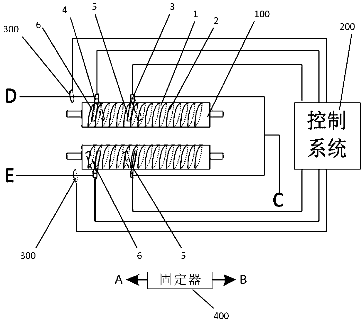
[0020] Please combine figure 1 As shown, this embodiment discloses a fuse assembly, including an adjustable fuse 100 , a control system 200 , a current Hall sensor 300 , and a holder 400 made of insulating material. The adjustable fuse 100 includes an insulating carrier 1 , a fuse 2 fixed on the insulating carrier 1 , and a sliding contactor; the fuse 2 extends along the length direction of the insulating carrier 1 . The two ends of the insulating carrier 1 are fixed on the A and B ends of the holder. And in this embodiment, the fuse 2 is spirally wound on the insulating carrier 1 . The sliding contactor has a joint in contact with the fuse 2 , and the joint moves back and forth along the length direction of the insulating carrier 1 to come into contact with different positions of the fuse 2 . The fuse 2 is a bare fuse body without an insulating layer on the outer layer. When the fuse 2 is wound on the insulating carrier 1, the distance between the fuse 2 needs to match the ...

Embodiment 2

[0025] This embodiment is the control method of the fuse assembly in the first embodiment above. In this control method: the current value signal detected by the current Hall sensor 300 is transmitted to the control system; the control system compares with the preset fusing current value and finds that When the current value signal does not meet the fusing requirement, the joints 5 and 6 of the sliding contactor are controlled to slide so that the fusing current reaches the preset fusing requirement.

[0026] As in Embodiment 1, when the fuse assembly includes at least two adjustable fuses 100, the two adjustable fuses are set to different fusing currents. When one of the adjustable fuses is blown, the other is adjustable. The fuse remains connected so that the continuity of the overall circuit is not interrupted.

[0027] And when an adjustable fuse is blown, control the joints 5 and 6 of the sliding contactor to move to the two ends of the unblown fuse 2, that is, avoid the ...

Embodiment 3

[0029] Embodiment 3 provides an adjustable fuse, which is an independent adjustable fuse in Embodiment 1. This independent adjustable fuse can be manufactured and used as a single product, and can be adjusted manually or automatically. The position where the joint of the sliding contactor is in contact with the fuse wire realizes the selection of different rated fusing currents. Since the adjustable fuse in this embodiment is exactly the same as the adjustable fuse in Embodiment 1, details are not repeated here.


PUM


Abstract

The invention relates to an adjustable fuse and a fuse assembly. The adjustable fuse comprises an insulating carrier, a fuse wire fixed on the insulating carrier, and a sliding contactor. The slidingcontactor is provided with a joint contacted with the fuse wire, and the joint moves back and forth along the length direction of the insulating carrier; therefore, the length of the fuse wire actually used in the fuse is changed, and the rated current value of the fuse is adjusted. A current Hall sensor is arranged, so that the current value on the fuse wire can be detected in real time, the rated current value of the fuse is correspondingly adjusted by controlling the joint of the sliding contactor to move according to the current value, and a more accurate overcurrent protection effect is provided for protected electrical equipment. The invention further provides a control method of the fuse assembly.

Description

technical field [0001] The invention belongs to the technical field of electronic devices, in particular to a fuse and a component containing the fuse. Background technique [0002] Fuses are commonly used electrical components that play a protective role in circuits. Generally, when the fuse circuit is overloaded, the fuse will be heated by the fusing current to quickly fuse the fuse to disconnect the circuit to realize circuit protection. Generally, a fuse has its own rated current capacity, which is determined by the metal parts that make up the fuse. With the development and popularization of smart devices, smart devices use a lot of batteries to facilitate the use of smart devices. In the main circuit of smart devices, the existing fuses that fuse the fuse by heating are used. Sometimes in order to better protect the circuit, two or more fuses need to be used in parallel. At the same time, the fixity of the fusing current determines the The protection of equipment is...

Claims


Application Information

Patent Timeline
Patent Type & Authority Applications(China)
IPC IPC(8): H01H85/04
CPCH01H85/04
Inventor 杨漫雪黄云周家兴
Owner NANJING SART SCI & TECH DEV
Why Eureka
Try Eureka