
A phase-locked loop control method and system based on a dynamic voltage restorer

A phase-locked loop and controller technology is applied in the field of phase-locked loop control methods and systems, and can solve the problems of reduced phase-locked loop control bandwidth and grid voltage drop.

Active Publication Date: 2021-11-05
江苏莱提电气股份有限公司
View PDF2 Cites 0 Cited by
  • Summary
  • Abstract
  • Description
  • Claims
  • Application Information

AI Technical Summary

Problems solved by technology

[0008] Based on this, it is necessary to provide a lock based on a dynamic voltage restorer that avoids power grid voltage sags in response to the above-mentioned reduction in the positive sequence voltage amplitude, resulting in a smaller control bandwidth of the phase-locked loop, which in turn leads to a grid voltage drop. phase loop control system

Method used


Image

  • A phase-locked loop control method and system based on a dynamic voltage restorer
  • A phase-locked loop control method and system based on a dynamic voltage restorer
  • A phase-locked loop control method and system based on a dynamic voltage restorer

Examples


Embodiment Construction

[0033] In order to make the object, technical solution and advantages of the present invention clearer, the present invention will be further described in detail below in conjunction with the accompanying drawings and embodiments. It should be understood that the specific embodiments described here are only used to explain the present invention, not to limit the present invention.

[0034] It should be noted that when an element is referred to as being “disposed on” another element, it may be directly on the other element or there may also be an intervening element. When an element is referred to as being "connected to" another element, it can be directly connected to the other element or intervening elements may also be present. The terms "vertical," "horizontal," "left," "right," and similar expressions are used herein for purposes of illustration only and are not intended to represent the only embodiments.

[0035]Unless otherwise defined, all technical and scientific term...


PUM


Abstract

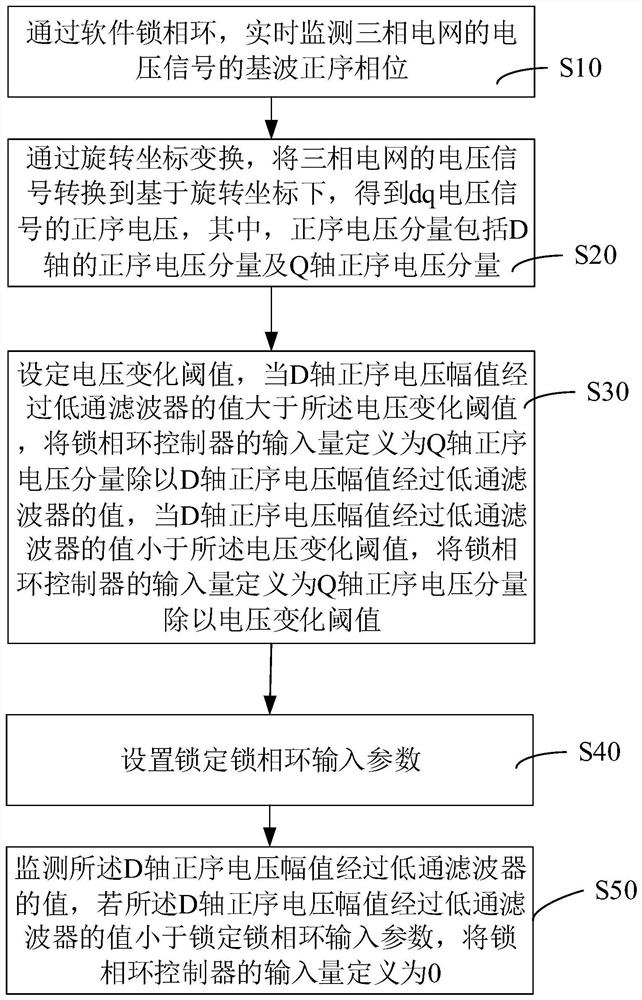
The invention discloses a phase-locked loop control method and system based on a dynamic voltage restorer, wherein the method includes: monitoring the fundamental positive-sequence phase of the voltage signal of a three-phase grid in real time through a software phase-locked loop; The voltage signal of the phase grid is converted to the coordinate based on the rotation, and the positive sequence voltage V of the dq voltage signal is obtained S +1 , where the positive sequence voltage component V S +1 Including the positive sequence voltage component V of the D axis sd + , and the Q-axis positive sequence voltage component V sq +1 ;Set voltage change threshold V ol_d_Min , when the D-axis positive sequence voltage amplitude passes through the low-pass filter, the value is greater than V ol_d_Min , the input quantity of the phase-locked loop controller is defined as when the value of the D-axis positive sequence voltage amplitude passing through the low-pass filter is less than the voltage change threshold V ol_d_Min , the V sq +1 / V ol_d_Min , the phase-locked loop control method of the above-mentioned dynamic voltage restorer is no longer affected by the change of the positive sequence voltage amplitude component, and solves the dynamic response problem of the traditional phase-locked loop when the mains power drops. It can not only take into account the steady state characteristics but also have good dynamic characteristics.

Description

technical field [0001] The invention relates to the field of automatic control, in particular to a dynamic voltage restorer-based phase-locked loop control method and system. Background technique [0002] Dynamic voltage restorer or DVR (hereinafter referred to as DVR), is a series or parallel compensation device with energy storage device (system), which has the ability to compensate active power in addition to reactive power. The application of modern power electronics technology can realize the control of power quality and provide users with specific power supply. [0003] The voltage of the computer system is disturbed and the short-term drop of the voltage on the load side (several cycles to dozens of cycles) is the main reason for the failure of sensitive loads and computer equipment. The dynamic voltage restorer (DVR) generates a compensation voltage within 1-2 milliseconds to offset the interference of the system voltage, so that the voltage on the load side does no...

Claims


Application Information

Patent Timeline
Patent Type & Authority Patents(China)
IPC IPC(8): H02J3/12
CPCH02J3/12
Inventor 袁帅刘快来王海鹏杜冬冬梁海龙
Owner 江苏莱提电气股份有限公司
Learn More