Electronic equipment, wireless charging state prompting method and computer readable storage medium

A technology for wireless charging and electronic equipment, applied in the field of electronic equipment and computer-readable storage media, can solve problems such as user troubles, inability to know the placement position of the electronic equipment in the wireless charging state, and poor signal meeting the wireless charging interaction specification, etc. To achieve the effect of resolving doubts or troubles

Pending Publication Date: 2020-08-07
HUNAN VOC ACOUSTIC TECH CO LTD
View PDF5 Cites 0 Cited by
  • Summary
  • Abstract
  • Description
  • Claims
  • Application Information

AI Technical Summary

Problems solved by technology

[0003] In view of this, the purpose of the embodiments of the present invention is to provide an electronic device, a method for prompting wireless charging status, and a computer-readable storage medium to solve the problem that when the wireless charging receiving chip fails to work normally, the MCU of the electronic device cannot know the wireless charging status. The charging status and the placement of electronic devices are relatively critical, causing the wireless charging receiving chip to work for a while at the beginning, but the signal does not meet the wireless charging interaction specifications very well, resulting in the termination of charging after a period of time, waiting for the user to think that charging When it is completed, it is found that it is not charged at all, which will cause troubles for users.

Method used


Image

  • Electronic equipment, wireless charging state prompting method and computer readable storage medium
  • Electronic equipment, wireless charging state prompting method and computer readable storage medium
  • Electronic equipment, wireless charging state prompting method and computer readable storage medium

Examples


Embodiment 1

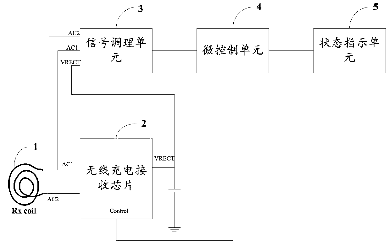
[0034] figure 1 It is a schematic structural diagram of the electronic device provided by Embodiment 1 of the present invention. For convenience of explanation, only the parts related to this embodiment are shown.

[0035] see figure 1 As shown, the electronic device provided by this embodiment includes a wireless charging receiving coil 1, a wireless charging receiving chip 2, a micro control unit 4, and a status indicating unit 5 that are electrically connected in sequence, and also includes an input terminal connected to the wireless charging receiving chip. The front-end pins of 2 are connected, and the output terminal is connected with the signal conditioning unit 3 of the micro control unit 4, wherein:

[0036] The signal conditioning unit 3 is used to detect the front-end signal of the wireless charging receiving chip 2, and extract the features of the front-end signal and output it to the micro-control unit 4;

[0037] The micro control unit 4 is used to detect the ...

Embodiment 2

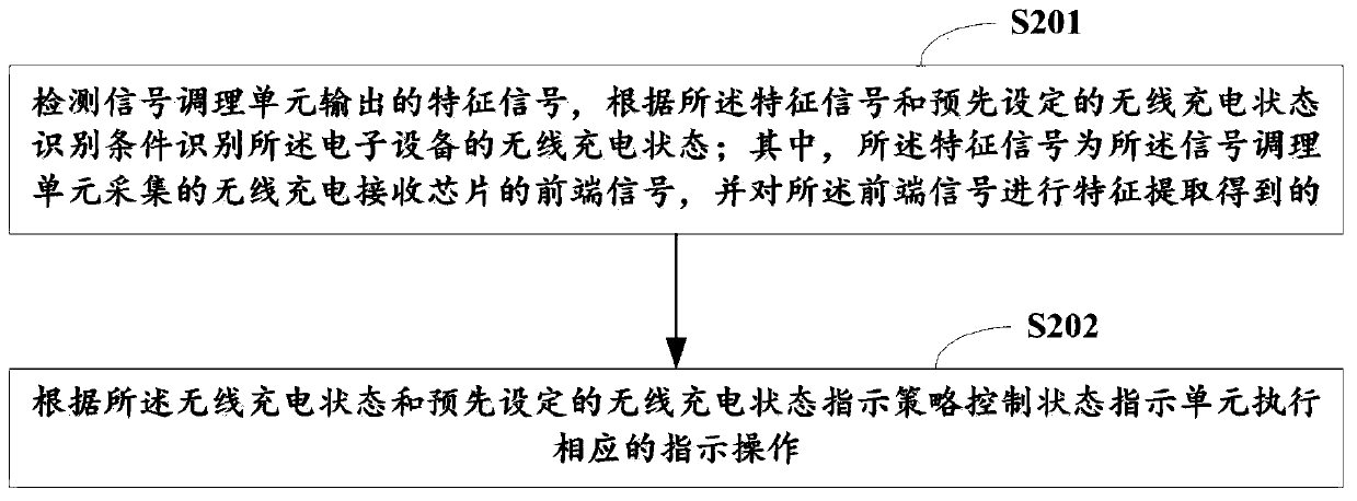
[0052] figure 2 It is the wireless charging state prompt method provided by the second embodiment of the present invention, which is applied to figure 1 electronics shown. see figure 2 As shown, the wireless charging state prompt method provided in this embodiment includes adopting figure 1 The microcontroller unit 4 in the shown electronic device performs the following steps:

[0053] Step S201, detect the characteristic signal output by the signal conditioning unit 3, and identify the wireless charging state of the electronic device according to the characteristic signal and the preset wireless charging state identification condition; wherein, the characteristic signal is the signal conditioning unit 3. Collecting the front-end signal of the wireless charging receiving chip 2, and performing feature extraction on the front-end signal;

[0054] Step S202, according to the wireless charging state and the preset wireless charging state indicating policy, the state indica...

Embodiment 3

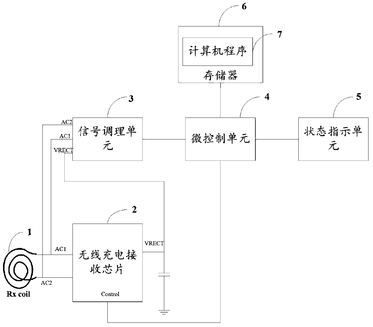
[0065] image 3 It is a schematic structural diagram of the electronic device provided by Embodiment 3 of the present invention. For convenience of explanation, only the parts related to this embodiment are shown.

[0066] see image 3 As shown, Embodiment 3 of the present invention provides an electronic device, which includes a wireless charging receiving coil 1, a wireless charging receiving chip 2, a micro control unit 4, and a status indicating unit 5 that are electrically connected in sequence, and also includes an input terminal and a The front-end pins of the wireless charging receiving chip 2 are connected, and the output end is connected to the signal conditioning unit 3 of the micro control unit 4;

[0067] It also includes a memory 6 electrically connected to the micro-control unit 4 and a computer program 7 stored on the memory 6 and operable on the micro-control unit 4, and the computer program 7 is controlled by the micro-control unit 4. When executing, reali...


PUM


Abstract

The invention discloses electronic equipment, a wireless charging state prompting method and a computer readable storage medium, which relate to the technical field of wireless charging. The electronic equipment comprises a wireless charging receiving coil, a wireless charging receiving chip, a micro-control unit and a state indication unit which are electrically connected in sequence, and furthercomprises a signal conditioning unit and a micro-control unit, wherein the input end of the signal conditioning unit is connected with a front-end pin of the wireless charging receiving chip, the output end of the signal conditioning unit is connected with the micro-control unit, and the signal conditioning unit is used for detecting a front-end signal of the wireless charging receiving chip andcarrying out feature extraction on the front-end signal; and the micro-control unit is used for detecting the characteristic signal of the front-end signal, identifying the wireless charging state ofthe electronic equipment according to the characteristic signal and a preset wireless charging state identification condition, and controlling the state indication unit to execute a corresponding indication operation. According to the embodiment of the invention, a user can clearly know whether the electronic equipment is reliably placed on the wireless charging device and can be normally chargedor not, and puzzles or troubles of the user are solved.

Description

technical field [0001] Embodiments of the present invention relate to the technical field of wireless charging, and in particular to an electronic device, a method for prompting a wireless charging state, and a computer-readable storage medium. Background technique [0002] The Microcontroller Unit (MCU) of traditional electronic equipment with wireless charging function generally detects the 5V voltage output pin or dedicated status indicator pin of the wireless charging receiving chip through a two-wire serial bus (Inter-Integrated Circuit, I2C). Whether to generate an interrupt signal to obtain the charging status of the wireless charging of the electronic device, and then control the corresponding light-emitting diode (Light Emitting Diode, LED) to turn on and off to inform the user whether the wireless charging status of the electronic device is normal. Although this method can realize whether the wireless charging of the electronic device is charging through the MCU, t...

Claims


Application Information

Patent Timeline
Patent Type & Authority Applications(China)
IPC IPC(8): H02J7/00H02J50/10H02J50/90H02J50/70
CPCH02J7/0047H02J50/10H02J50/70H02J50/90
Inventor 何亮夏波詹昌寿粟新国
Owner HUNAN VOC ACOUSTIC TECH CO LTD
Why Eureka
Try Eureka