Seat waist synchronous linkage device for seat and seat

A technology of synchronous linkage and seat waist, which is applied in home appliances, other seat furniture, applications, etc., can solve the problem that the seat lumbar support cannot reach the waist, and achieve the effect of simple structure, which is conducive to modular production and popularization and application

Inactive Publication Date: 2020-08-11
ANJI YONGYI SHANGPIN FURNITURE CO LTD
View PDF3 Cites 2 Cited by
  • Summary
  • Abstract
  • Description
  • Claims
  • Application Information

AI Technical Summary

Problems solved by technology

[0007] The present invention overcomes the deficiencies in the above prior art, and provides a seat waist synchronous linkage device, which not only solves the problem that the seat lumbar cannot support the waist, but also the seat waist device lumbar When moving forward, the lumbar support will not tilt downward, but will be supported horizontall...

Method used


Image

  • Seat waist synchronous linkage device for seat and seat
  • Seat waist synchronous linkage device for seat and seat
  • Seat waist synchronous linkage device for seat and seat

Examples


Embodiment 1

[0083] Embodiment 1: First, define the reference orientations of the components of the present invention. In the present invention, when the seat is installed and used normally, the front of the seat is the front end and the head, and the rear of the seat, including the position of the seat lumbar, is the rear end, tail.

[0084] The seat waist synchronous linkage device for the seat of the present embodiment, such as Figure 7-22 shown, including:

[0085] The base 1 is used to support the whole device; the base 1 is fixed.

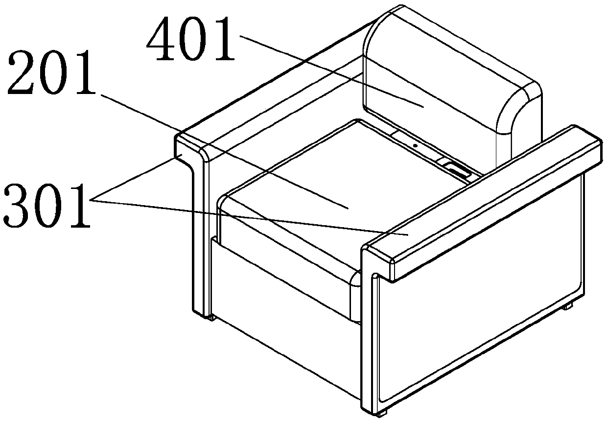
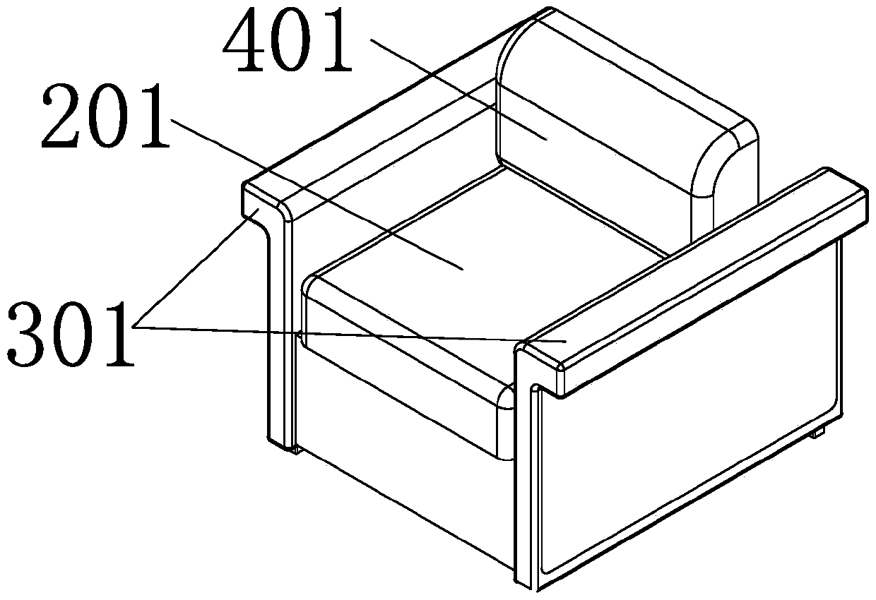
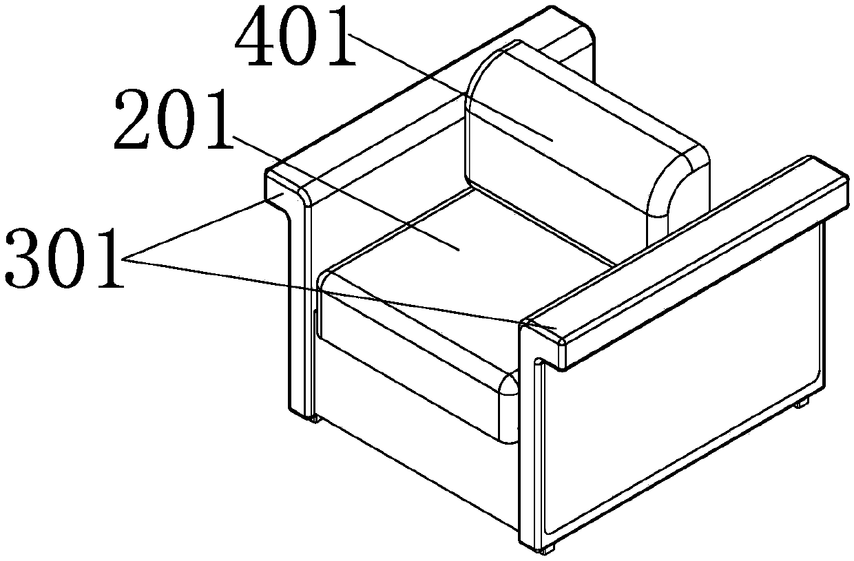
[0086] The seat frame 2 is used to configure the seat cushion, and the seat frame is arranged above the base;

[0087] The front and rear connecting rods 3a and 3b are all symmetrically arranged on the left and right sides of the base 1, wherein the two ends of the front connecting rod 3a are respectively hinged with the front end of the seat frame 2 and the front end of the base 1, and the two ends of the rear connecting rod 3b are respectively connec...

Embodiment 2

[0105] Example 2: Figure 23-27 Another embodiment of the device of the present invention is illustrated. The difference from Embodiment 1 is that the lumbar support 4 is slidably connected to the base 1, and the drive shaft 8c and the limit shaft 8d are all on the base 1. The connecting rod of this embodiment Group 8 is specifically 4 connecting rods.

[0106] In specific applications, that is, when the human body is sitting, the seat frame 2 in this embodiment moves down after receiving the pressure of the human body, driving the front and rear connecting rods 3a, 3b hinged with the front and rear ends of the seat frame 2, and the front and rear connections During the downward movement of the rods 3a and 3b, the connecting rod group 8 is squeezed to make it stretch and expand, and the connecting rod group 8 stretches through the drive shaft 8c to transmit the pulling force to the transverse support 4b of the lumbar support 4, and the transverse support 4b of the lumbar suppo...


PUM


Abstract

The invention discloses a seat waist synchronous linkage device for a seat and the seat. The seat waist synchronous linkage device comprises a base, a seat frame arranged above the base. A front connecting rod, a rear connecting rod, the base and the seat frame form a four-connecting-rod mechanism, and the seat frame can move relative to the base under the supporting and guiding effects of the front connecting rod and the rear connecting rod and perform state conversion between a no-load position and a sitting position. The device also comprises a waist support connected with the seat frame orthe base in a sliding mode, wherein the waist support is provided with an initial position and a waist jacking position; and a sliding guide mechanism which drives the waist support to slide along one of the seat frame or the base, and correspondingly, relative displacement is generated between the waist support and one of the seat frame or the base. The stroke of the waist support relative to the base in the horizontal direction is larger than that of the seat frame relative to the base, the stroke of the waist support is larger, so that the waist of a human body can be quickly jacked when the human body sits, and the purpose of supporting the waist is achieved.

Description

technical field [0001] The invention relates to the technical field of chairs, in particular to a seat waist synchronous linkage device used for the seat and the seat. Background technique [0002] When a person sits down on the existing seat, the waist of the person who sits in the back generally needs to be close to the backrest, and the waist of the person who sits forward cannot touch the seat, resulting in that the waist cannot be supported; The back cushion is used to support the waist. Although this method can play a certain role, it is not convenient enough and it is troublesome to carry. [0003] French invention patent FR2045120 discloses a linkage system of a seat cushion and a backrest. Figure 1-4 As shown, the linkage system applies the principle of leverage, in which the rod 6 is the power arm, and the rod 4 is the resistance arm. When a person sits down and presses the seat panel 7, the rod 6 moves downward after being pressed, and the rod 4 revolves around t...

Claims


Application Information

Patent Timeline
IPC IPC(8): A47C7/14A47C7/44A47C7/46A47C20/10
CPCA47C7/14A47C7/443A47C7/462A47C20/10
Inventor 何基虞红潮蒋小兵
Owner ANJI YONGYI SHANGPIN FURNITURE CO LTD
Why Eureka
Try Eureka