Craniofacial state analysis method and device and electronic equipment

An analysis method and craniofacial technology, applied in medical science, sensors, diagnostic recording/measurement, etc., can solve problems such as large errors in the determination process and inability to obtain craniofacial status

Active Publication Date: 2020-08-11
赤峰学院附属医院
View PDF5 Cites 8 Cited by
  • Summary
  • Abstract
  • Description
  • Claims
  • Application Information

AI Technical Summary

Problems solved by technology

[0004] The embodiment of the present invention provides a craniofacial state analysis method, device, and electronic equipment to at least solve the defect in the related art that there is a large error in the process of determining the midsagittal plane of the cranium and maxillofacial plane due to the irregularity of the skull , causing technical problems in obtaining a comprehensive craniofacial status

Method used


Image

  • Craniofacial state analysis method and device and electronic equipment
  • Craniofacial state analysis method and device and electronic equipment

Examples


Embodiment 1

[0029] According to an embodiment of the present invention, an embodiment of a craniofacial state analysis method is provided. It should be noted that the steps shown in the flow chart of the accompanying drawings can be executed in a computer system such as a set of computer-executable instructions, Also, although a logical order is shown in the flowcharts, in some cases the steps shown or described may be performed in an order different from that shown or described herein.

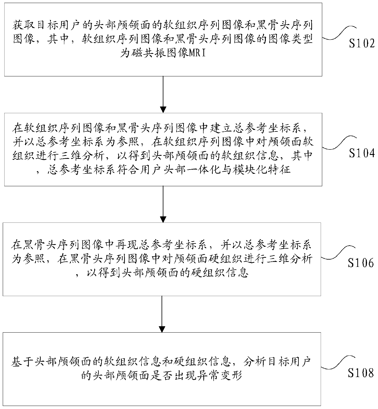
[0030] figure 1 is a schematic diagram of an optional craniofacial state analysis method according to an embodiment of the present invention, such as figure 1 As shown, the method includes the following steps:

[0031] Step S102, acquiring craniomaxillofacial soft tissue sequence images and black bone sequence images of the head of the target user, wherein the image type of the soft tissue sequence images and black bone sequence images is magnetic resonance image MRI;

[0032] Step S104, establish a to...

Embodiment 2

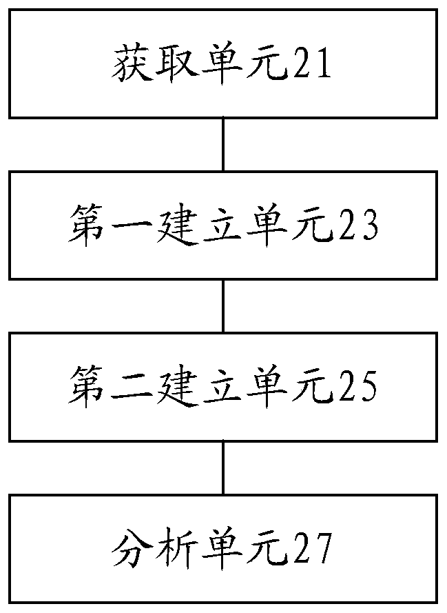
[0063] figure 2 It is a schematic diagram of an optional craniofacial analysis device according to an embodiment of the present invention, such as figure 2 As shown above, the analysis device includes: an acquisition unit 21, a first establishment unit 23, a second establishment unit 25, and an analysis unit 27, wherein,

[0064] The acquiring unit 21 is configured to acquire the soft tissue sequence images and the black bone sequence images of the craniomaxillofacial region of the target user, wherein the image type of the soft tissue sequence images and the black bone sequence images is magnetic resonance image MRI;

[0065] The first establishing unit 23 is used to establish a total reference coordinate system in the soft tissue sequence images and black bone sequence images, and use the total reference coordinate system as a reference to perform three-dimensional analysis on the craniofacial soft tissue in the soft tissue sequence images to obtain head The soft tissue i...


PUM


Abstract

The invention discloses a craniofacial state analysis method and device and electronic equipment. The analysis method comprises the steps of obtaining head craniofacial parenchyma sequential images and black bone sequential images of an object user; establishing a total reference coordinate system in the parenchyma sequential images and the black bone sequential images, and using the total reference coordinate system as reference, performing three-dimensional analysis on craniofacial parenchyma in the parenchyma sequential images to obtain head craniofacial parenchyma information, wherein thetotal reference coordinate system conforms to integrated and modularized characteristics of the head of the user; reproducing the total reference coordinate system in the black bone sequential images,using the total reference coordinate system as reference, and performing three-dimensional analysis on craniofacial sclerous tissues in the black bone sequential images to obtain craniofacial sclerous tissue information of the head; and based on the craniofacial parenchyma information and the sclerous tissue information of the head, analyzing whether the head craniofacial of the object use generates abnormal deformation.

Description

technical field [0001] The present invention relates to the technical field of cephalometric analysis, in particular to a craniomaxillofacial status analysis method, device, and electronic equipment. Background technique [0002] In related technologies, in terms of clinical imaging, especially the continuous popularization of CBCT (Cone beam computed tomography, CBCT), it is easy to obtain three-dimensional data reflecting the user's craniofacial information through computer terminals. In , the establishment of three-dimensional coordinate system and reference plane is very important. In the current technical scheme, when determining the mid-sagittal plane of the craniofacial plane, three anatomical landmarks located on the midline of the cranio-maxillofacial plane are often used to construct the mid-sagittal plane, that is, the orbito-ear plane is first constructed as the axial plane (the horizontal plane ), and then choose two anatomical landmarks on the midline of the f...

Claims


Application Information

Patent Timeline
Patent Type & Authority Applications(China)
IPC IPC(8): A61B5/055A61B5/107A61B5/00
CPCA61B5/004A61B5/055A61B5/1073A61B5/1075A61B5/1077A61B5/1079A61B5/4542
Inventor 姜喜玲付明山张敏
Owner 赤峰学院附属医院
Why Eureka
Try Eureka