Combined heat and power generation coupling heat supply load adjusting method and system

A technology of heating system and load regulation, applied in heating system, space heating and ventilation details, household heating, etc., can solve the problem of not considering the change of heating network load, etc.

Active Publication Date: 2020-08-11
HUADIAN ELECTRIC POWER SCI INST CO LTD
View PDF9 Cites 5 Cited by
  • Summary
  • Abstract
  • Description
  • Claims
  • Application Information

AI Technical Summary

Problems solved by technology

But in general, the heating load is affected by the outdoor ambient temperature, ambient humidity, solar radiation, wind speed, indoor temperature, pipe network characteristics and building characteristics. According to Swedish scholars, the heat loss of the pipe network can increase the heat load by 5%. -8%, the wind speed can increase the heat load by 1%-4%. In addition, the comprehensive factors of the building (including building characteristics and indoor environmental factors) have a huge impact on the heat load. It can be seen that the application numbers are 201510889154.5 and The prediction method announced by the patented technology of 201610415738.3 still has certain drawbacks
The patented technology with application number 201711498480.9 does not consider the change of the heating network load, but only adjusts the electric and thermal load matching adjustment of the heating system through the operation adjustment of the thermal power unit itself

Method used


Image

  • Combined heat and power generation coupling heat supply load adjusting method and system
  • Combined heat and power generation coupling heat supply load adjusting method and system
  • Combined heat and power generation coupling heat supply load adjusting method and system

Examples


Embodiment Construction

[0092] The present invention will be further described in detail below in conjunction with the accompanying drawings and examples. The following examples are explanations of the present invention and the present invention is not limited to the following examples.

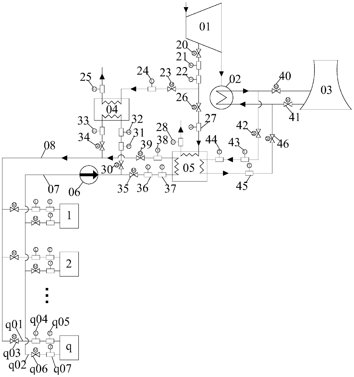
[0093] see figure 1 , this embodiment relates to a heat and power cogeneration coupled heating load adjustment method and system based on the heat load prediction of the heat network. The absorption heat pump 05, the heat network circulating water pump 06, the heat network return pipe 07 and the heat network water supply pipe 08, the exhaust port of the thermal power unit 01 is connected to the condenser 02, and the circulating water side of the condenser 02 is connected to the absorption heat pump at the same time The low-temperature heat source side of 05 is connected to the cooling tower 03, and a third circulation valve 42, a first circulation flow meter 43 and a first circulation temperature meter 44 are sequen...


PUM


Abstract

The invention discloses a combined heat and power generation coupling heat supply load adjusting method and system and belongs to the technical field of centralized heat supply. A heat supply system comprises thermoelectric unit, a condenser, a cooling tower, a first station of a heat supply network, an absorption heat pump, a circulating water pump of the heat supply network, an electric adjusting valve, an Internet of things flowmeter, an Internet of things thermograph, an Internet of things pressure gauge and q heating stations, wherein q is greater than or equal 2. By considering influenceof factors such as meteorological parameters, pipeline characteristics, building characteristics and heat user characteristics comprehensively, a heat supply network heat load prediction model is established to predict a heat supply network heat load precisely. By combining a thermoelectric decoupling ability of the adsorption heat pump, on the one hand, the operating working condition of the thermoelectric unit is arranged reasonably to adjust electric and heat loads of units on a heat source side, and on the other hand, precise operation adjustment of heat supply on the heat supply networkside is achieved, so that the heating demand of the heat user is met effectively, and the combined heat and power generation coupling heat supply load adjusting method has relatively high actual application value.

Description

technical field [0001] The invention relates to the technical field of central heating, in particular to a heat and power cogeneration coupled heating load adjustment method and system based on heat load prediction of a heating network. Background technique [0002] The central heating system is one of the city's infrastructure and one of the signs of the city's modernization level. The central heating industry is developing rapidly in my country. By the end of 2016, the area of ​​central heating in my country was about 7 billion square meters, of which the area of ​​central heating with combined heat and power generation was about 3.5 billion square meters. The high-quality development of the central heating system is directly related to the urban development. modernization and the improvement of people's living standards. For the cogeneration central heating system, it not only shoulders the heating demand on the heating network side, but also shoulders the power generatio...

Claims


Application Information

Patent Timeline
IPC IPC(8): F24D19/10
CPCF24D19/1039F24D19/1048
Inventor 高新勇黄平平郑立军李成磊
Owner HUADIAN ELECTRIC POWER SCI INST CO LTD
Why Eureka
Try Eureka