
Electronic equipment

A technology for electronic equipment and electrical connection, which is applied in the field of communication and can solve problems such as signal loss of electronic equipment

Active Publication Date: 2022-01-04
GUANGDONG OPPO MOBILE TELECOMM CORP LTD
View PDF19 Cites 0 Cited by
  • Summary
  • Abstract
  • Description
  • Claims
  • Application Information

AI Technical Summary

Problems solved by technology

[0003] One purpose of the present disclosure is to solve the technical problem in the prior art that the surface wave generated by the back cover of the electronic device causes loss of the signal of the electronic device

Method used


Image

  • Electronic equipment
  • Electronic equipment
  • Electronic equipment

Examples


Embodiment Construction

[0022] While the present disclosure may readily be embodied in different forms, only some of these are shown in the drawings and will be described in detail in this specification, with the understanding that the specification should be considered as the It is an exemplary illustration of the principles of the disclosure and is not intended to limit the disclosure to what is described herein.

[0023] Therefore, a feature indicated in this specification will be used to describe one feature of an embodiment of the present disclosure, rather than implying that every embodiment of the present disclosure must have the described feature. Furthermore, it should be noted that this specification describes a number of features. Although certain features may be combined to illustrate possible system designs, these features may also be used in other combinations not explicitly described. Thus, the illustrated combinations are not intended to be limiting unless otherwise stated.

[0024]...


PUM


Abstract

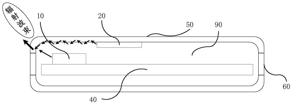
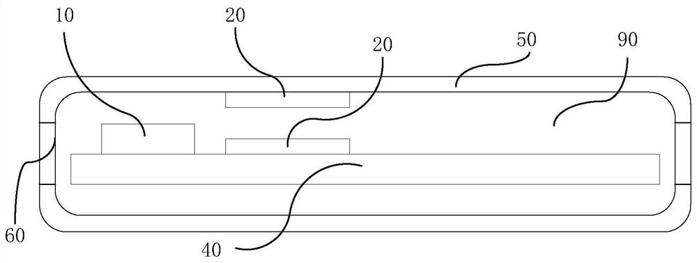
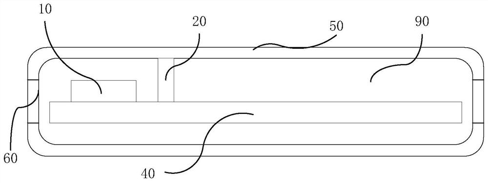
The present disclosure provides an electronic device, comprising: a main board; a back cover covering the main board and forming an accommodating cavity with the main board; at least one antenna assembly disposed in the accommodating cavity and connected with the main board Electrical connection; at least one reflection structure is fixed on the side of the back cover facing the main board, and is arranged on one side of the antenna assembly, the reflection structure is used to reflect the surface wave formed by the antenna assembly, and The surface wave is superimposed with the signal wave of the antenna assembly. The technical problem in the prior art that the surface wave generated by the back cover of the electronic device causes signal loss of the electronic device is solved.

Description

technical field [0001] The present disclosure relates to the technical field of communications, and in particular to an electronic device. Background technique [0002] At present, due to the addition of various components and various extreme design schemes, more and more electronic devices in which the antenna radiator is arranged inside the device appear on the market. However, this arrangement will cause the signal wave of the antenna assembly to pass through the back cover of the electronic device. When the signal wave passes through the back cover, a surface wave will be generated at the back cover, and the surface wave will cause energy loss and loss of the signal wave of the antenna assembly, reducing the radiation efficiency and gain of the antenna assembly. Contents of the invention [0003] An object of the present disclosure is to solve the technical problem in the prior art that the surface wave generated by the back cover of the electronic device causes loss ...

Claims


Application Information

Patent Timeline
Patent Type & Authority Patents(China)
IPC IPC(8): H01Q15/14H01Q1/22
CPCH01Q15/14H01Q1/22
Inventor 雍征东
Owner GUANGDONG OPPO MOBILE TELECOMM CORP LTD
Learn More