Plug connector and connector combination with same

A plug connector and connector combination technology, which is applied to the parts, connections, and two-part connection devices of the connecting device, can solve the problems of unfavorable thinness, fatigue of the spring arm, and high plug connector, so as to suppress fatigue and ensure The effect of service life

Active Publication Date: 2020-08-11
DEYI PRECISION ELECTRONIC IND CO LTD PANYU
View PDF8 Cites 0 Cited by
  • Summary
  • Abstract
  • Description
  • Claims
  • Application Information

AI Technical Summary

Problems solved by technology

[0003] Since the distance between the two buckle parts and the place where the first arm is connected to the main body is smaller than the distance between the two buckle parts and the pressing part, when the pressing part is pressed down, When the pressing part moves downward for a relatively large distance, the two buckling parts move down a relatively small distance. Therefore, in order to realize the mutual release of the buckling part and the locking groove, the pressing The part needs to move down a large enough distance, but this will cause the elastic arm to fatigue or even break due to excessive pressing, so that the locking function cannot be realized, and such a structure needs to give the second arm a certain distance. The top surface of the main body is high enough to facilitate its deformation, but this will lead to a relatively high design of the plug connector, which is not conducive to thinning

Method used


Image

  • Plug connector and connector combination with same
  • Plug connector and connector combination with same
  • Plug connector and connector combination with same

Examples


Embodiment Construction

[0046] In order to facilitate a better understanding of the purpose, structure, features, and effects of the present invention, the present invention will now be further described in conjunction with the accompanying drawings and specific embodiments.

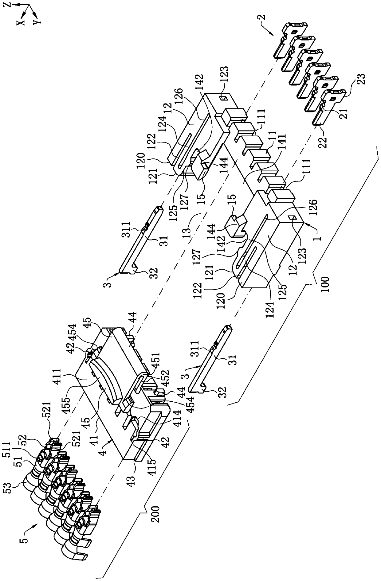
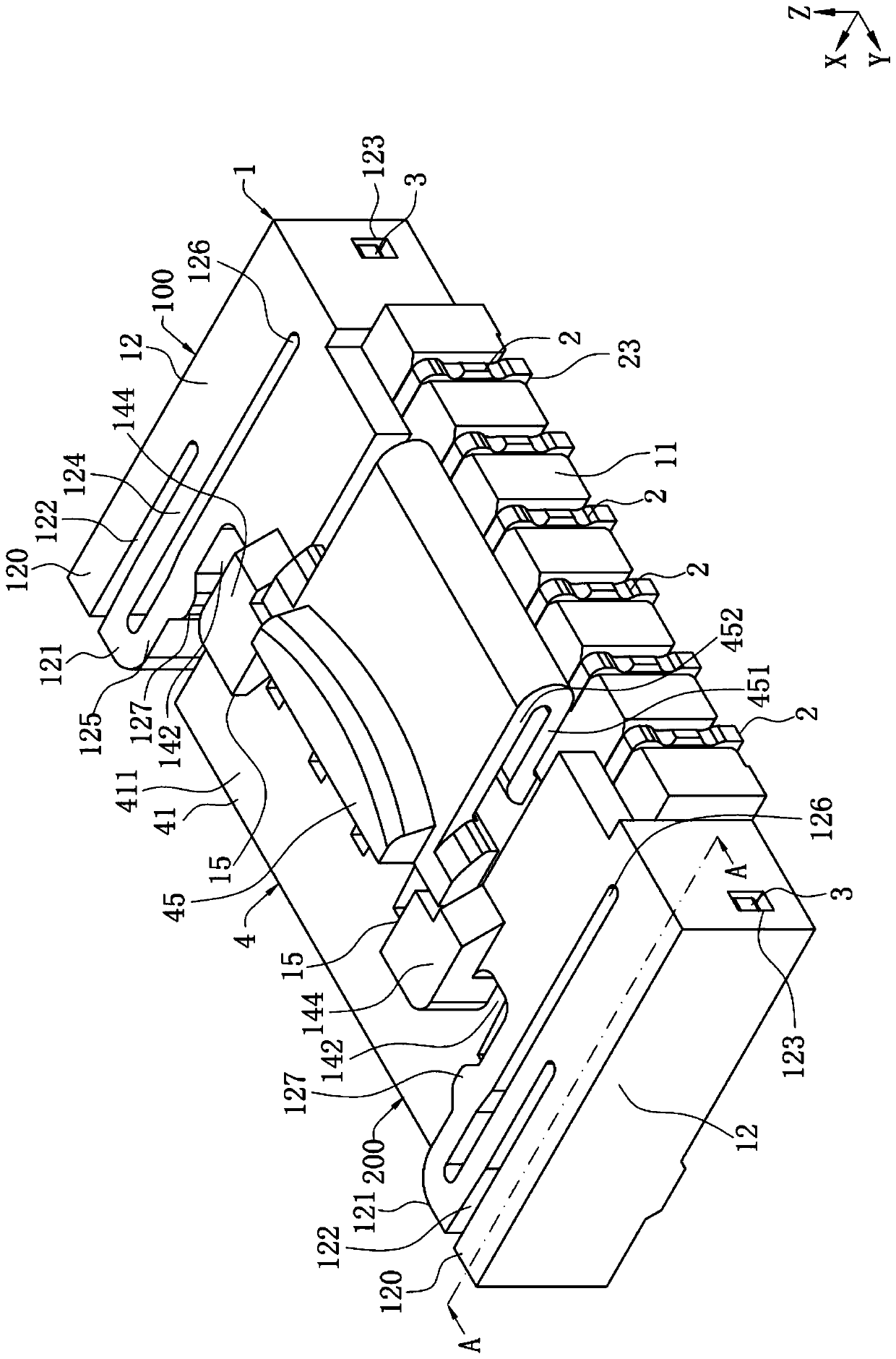
[0047] Such as figure 1 and figure 2 As shown, the plug connector 200 of the present invention and the connector combination having the plug connector 200 are shown. Define the forward direction in the front-back direction as the positive direction of the X-axis, the leftward direction in the left-right direction as the positive direction of the Y-axis, and the upward direction in the up-down direction as the positive direction of the Z-axis.

[0048] Such as figure 1 , figure 2 and Figure 10 Shown is the plug connector 200 of the present invention and the connector assembly having the plug connector 200, the connector assembly includes a receptacle connector 100 and a plug connector 200, and the receptacle connector 100...


PUM


Abstract

The invention discloses a plug connector which is used for being backwards inserted into a socket connector. The connector comprises: an insulating body, wherein the insulating body comprises a main body part and a lock catch arm formed by extending from the top surface of the main body part, the left side and the right side of the front end of the lock catch arm laterally protrude and extend to form lock catch parts respectively to mutual locking and buckling with the buckling part of the socket connector, the locking and buckling part is located in front of the joint of the locking arm and the main body part, the front end of the lock catch arm protrudes upwards between the two locking parts to form a pressing part, and the pressing part is aligned with the locking part in the left-rightdirection; at least one butting terminal which is arranged at the insulating body, wherein each butt joint terminal is provided with a butt joint part used for being connected with at least one conductive terminal of the socket connector in a conductive mode, the locking and buckling part is moved downward for a large distance, so that the locking and buckling part and the corresponding bucklingparts can be separated from each other under the condition that the deformation quantity of the locking and buckling part is very small, and the situation that locking and buckling arm is fatigued andeven broken due to excessive pressing is restrained.

Description

【Technical field】 [0001] The present invention relates to a plug connector and a connector combination with the plug connector, in particular to a connector combination that locks a receptacle connector through a locking arm of the plug connector. 【Background technique】 [0002] There is a plug connector and a socket connector docked with it. The plug connector and the socket connector form a connector combination. The socket connector includes an insulating seat and a plurality of conductive terminals arranged on the insulating seat. The insulating seat The seat is provided with a docking space recessed from its front end to the rear, a top wall above the docking space, and two card slots that penetrate the top wall upwards and are spaced apart in the left and right directions. The device includes an insulating body and a plurality of butt terminals arranged on the insulating body. The insulating body is provided with a main body and an elastic arm connected to the main bod...

Claims


Application Information

Patent Timeline
IPC IPC(8): H01R13/627H01R13/629H01R13/10H01R13/04H01R13/20
CPCH01R13/6272H01R13/629H01R13/10H01R13/04H01R13/20H01R13/6273H01R13/639H01R13/432H01R13/41H01R24/60
Inventor 张文昌杨启晓陈志坤
Owner DEYI PRECISION ELECTRONIC IND CO LTD PANYU
Why Eureka
Try Eureka