Blade and image forming apparatus incorporating same
A scraper and component technology, which is applied in the field of scraper components and image forming devices, can solve the problems of faster vibration speed of the cleaning scraper, and achieve the effects of suppressing abnormal sound and fatigue
- Summary
- Abstract
- Description
- Claims
- Application Information
AI Technical Summary
Problems solved by technology
Method used
Image

Examples
Embodiment 1
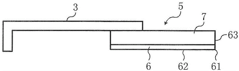
[0077] As the cleaning blade of embodiment 1, such as figure 1 As shown, a cleaning blade formed of a two-layer construction of an edge layer and a support layer is used. The thickness of the edge layer is 0.5 mm, and the thickness of the support layer is 1.3 mm. In addition, the elastic power of the edge layer is 82%, the elastic power of the support layer is 91%, and the elastic power of the support layer is greater than that of the edge layer.
[0078] In Example 1, the linear pressure drop after leaving for 168 hours in a state where the cleaning blade was brought into contact with the image carrier as the member to be contacted was 2.3 g / cm. This is a value smaller than the line pressure drop of 4.0g / cm (20% of the set line pressure) caused by the line pressure drop in the MPC3503 machine, and it is not a line pressure drop that affects cleanability .
[0079] The reason why the decrease in cleanliness due to fatigue can be suppressed is considered as follows.
[0080...
Embodiment 2-14
[0084] For the cleaning blades of Examples 2-14, the elastic power of the edge layer and the elastic power of the support layer were changed to the values shown in Table 1 from the configuration of Example 1.
[0085] The magnitude relationship of the elastic power of the edge layer and the support layer in the cleaning blade of Examples 2-14 is the same as that of Example 1, and can suppress the abnormal sound generated by the sliding movement between the abutting member and the edge and the duration of time. fatigue that occurs in Since the reason for obtaining such an evaluation is the same as in Example 1, description thereof will be omitted.
Embodiment 2-4
[0145] Because the cleaning blade of embodiment 2-14 is the same as embodiment 1, the martens hardness of edge layer is at 1.0N / mm 2 As described above, it is possible to suppress filming of the toner admixture on the surface of the image carrier.
[0146] In addition, since the Martens hardness of the edge layer is higher than that of the supporting layer, even if the hardness of the edge layer is high enough to maintain the removal ability of the surface of the abutted member, it is possible to maintain the relative relative strength of the entire scraper against the surface of the abutted member. The followability of the surface shape of the contact member.
[0147] Since the reason for obtaining such an evaluation is the same as in Example 1, description thereof will be omitted.
[0148] (comparative example 1)
[0149] The cleaning blade of Comparative Example 1 is a single-layer cleaning blade, and the Martens hardness of the edge is 1.0 N / mm 2 the following.
[0150...
PUM
| Property | Measurement | Unit |
|---|---|---|
| hardness | aaaaa | aaaaa |
| hardness | aaaaa | aaaaa |
| hardness | aaaaa | aaaaa |
Abstract
Description
Claims
Application Information
 - R&D
- Intellectual Property
- Life Sciences
- Materials
- Tech Scout
- Unparalleled Data Quality
- Higher Quality Content
- 60% Fewer Hallucinations
Browse by: Latest US Patents, China's latest patents, Technical Efficacy Thesaurus, Application Domain, Technology Topic, Popular Technical Reports.
© 2025 PatSnap. All rights reserved.Legal|Privacy policy|Modern Slavery Act Transparency Statement|Sitemap|About US| Contact US: help@patsnap.com