Motor, Motor device and pointer type display device

A motor, unconfigured technology, applied in the direction of electromechanical devices, electrical components, etc., can solve the problems of reducing bearing life, abnormal sound and so on

Inactive Publication Date: 2015-09-09
SANKYO SEIKI MFG CO LTD
View PDF6 Cites 0 Cited by
  • Summary
  • Abstract
  • Description
  • Claims
  • Application Information

AI Technical Summary

Problems solved by technology

As a result, the rotor vibrates, causing causes

Method used


Image

  • Motor, Motor device and pointer type display device
  • Motor, Motor device and pointer type display device
  • Motor, Motor device and pointer type display device

Examples


Embodiment approach 1

[0057] (The overall structure of the motor unit)

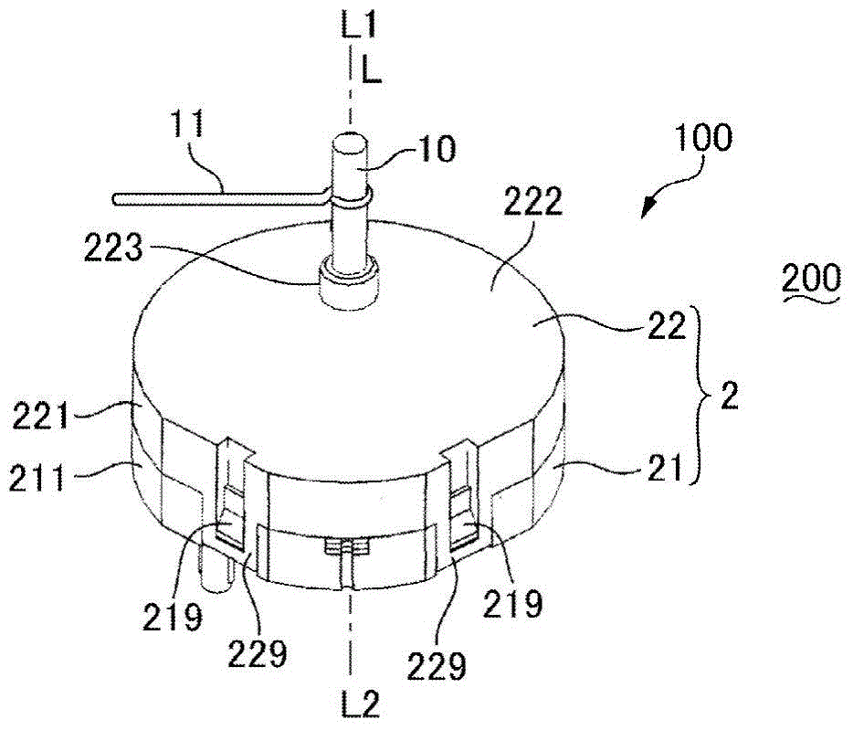
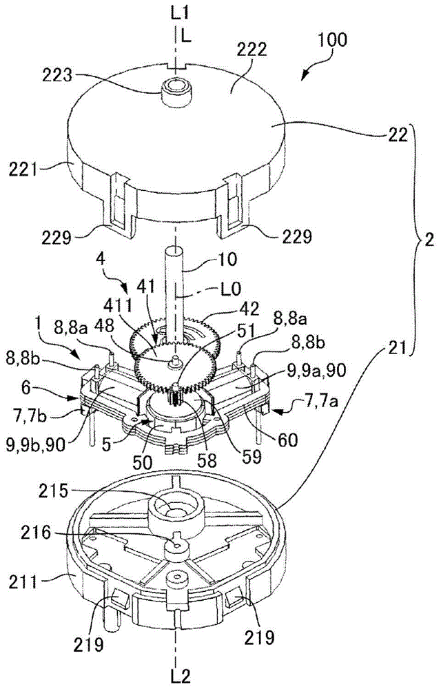
[0058] 1( a ) and FIG. 1( b ) are explanatory diagrams of a motor device 100 according to Embodiment 1 of the present invention, and FIG. As a perspective view, FIG. 1( b ) is an exploded view of the motor device 100 . In addition, in the following description, the side where the output shaft 10 protrudes in the direction in which the axis L of the output shaft 10 extends is taken as one side L1, and the side opposite to the side where the output shaft 10 protrudes is taken as the other side. One side L2. In addition, the axis of the rotor 5 in the motor 1 is defined as the rotation center axis L0. In addition, for the sake of convenience, one side of the rotation center axis L0 is also referred to as one side L1, and the other side of the rotation center axis L0 is also described as the other side L2.

[0059] The motor device 100 shown in FIG. 1( a ) and FIG. 1( b ) has a structure in which the output shaft 10 (output mem...

Embodiment approach 2

[0104] Figure 7 This is an explanatory diagram schematically showing the air gap between the salient pole 61 and the magnet 50 in the motor 1 applied to the motor device 100 according to Embodiment 2 of the present invention. In addition, since the basic structure of this embodiment is the same as that of Embodiment 1, the same code|symbol is attached|subjected and shown to a common part, and their description is abbreviate|omitted.

[0105] like Figure 7 As shown, in this embodiment, when the first gap g1 is narrower than the second gap g2, the end portions 610c, 610d, 610e of the first auxiliary poles (salient poles 61c, 61d, 61e) and the second auxiliary poles The end portion 610a of the pole (salient pole 61a) is located on an imaginary circle C inscribed with the end portions 610f, 610b of the two main poles (salient poles 61f, 61b). The center Co deviates toward the two main poles (salient poles 61f, 61b). In the present embodiment, the rotation center axis L0 of th...

Embodiment approach 3

[0116] Figure 9 It is an explanatory diagram schematically showing the air gap between the salient pole 61 and the magnet 50 in the motor 1 applied to the motor device 100 according to Embodiment 3 of the present invention. In addition, since the basic structure of this embodiment is the same as that of Embodiment 1, the same code|symbol is attached|subjected and shown to a common part, and their description is abbreviate|omitted.

[0117] like Figure 9 As shown, in this embodiment, the S poles and N poles of the magnet 50 are arranged at equal angular intervals on the outer peripheral surface in such a manner that they alternate along the circumferential direction. In the present embodiment, five pairs of S poles and N poles of the magnet 50 are formed. Therefore, in the magnet 50 , a total of ten S poles and N poles are formed at equal angular intervals, so that the angular positions between adjacent S poles and N poles in the circumferential direction differ by 36°.

...


PUM


Abstract

The invention provides a motor capable of restraining a rotor to radially vibrate, a motor device with the motor and a pointer type display device. In the motor, coils are configured at the respective periphery of two salient poles (61f, 61b) (main poles) arranged in a first angle region (theta1) less than 180 degrees among a plurality of salient poles (61) of a stator iron core. And the salient poles (61c to 61e) in a second angle region (theta2) of 180 degrees among the plurality of salient poles (61) are first assisting poles which are not provided with coils at the periphery. At the opposite side to the two main poles (the salient poles 61f, 61b) side, the second angle region (theta2) takes an extension line of two bisectrixes as a center. The bisectrixes divide the first angle region (theta1) into two equal parts. A first interval (g1) between the main poles (the salient poles 61f, 61b) and a magnet is narrower than a second internal (g2) between the first assisting poles (the salient poles 61c to 61e) and the magnet.

Description

technical field [0001] The present invention relates to a motor, a motor device, and an analog display device in which coils are wound on two salient poles of a plurality of salient poles of a stator core provided along a peripheral surface of a magnet. Background technique [0002] In a display device such as a meter device for an automobile, a structure in which a pointer is attached via a motor is adopted. On the other hand, as a motor, there is provided a structure in which a plurality of salient poles of a stator core are arranged along the peripheral surface of a magnet, and coils are wound on two of the plurality of salient poles (see Patent Document 1). [0003] Patent Document 1: Japanese Patent Laid-Open No. 2005-333786 [0004] In the motor described in Patent Document 1, when the rotor rotates, forces act on the rotor from two radial directions perpendicular to the rotation center axis of the rotor. Also, the force acting on the rotor from the radial direction ...

Claims


Application Information

Patent Timeline
IPC IPC(8): H02K37/16
Inventor 保科哲夫
Owner SANKYO SEIKI MFG CO LTD
Why Eureka
Try Eureka