
Quick clamping system

A fast, clamping technology, applied in the direction of clamping, positioning device, support, etc., can solve problems such as piston stuck clamping function, piston wear and loss, etc.

Inactive Publication Date: 2018-12-07
SHANGHAI DINGXIN ELECTROMECHANICAL EQUIP
View PDF4 Cites 6 Cited by
  • Summary
  • Abstract
  • Description
  • Claims
  • Application Information

AI Technical Summary

Problems solved by technology

[0005] The main purpose of the present invention is to provide a quick clamping system to solve the problems of piston wear, piston jamming and unstable or even loss of clamping function

Method used


Image

  • Quick clamping system

Examples


Embodiment Construction

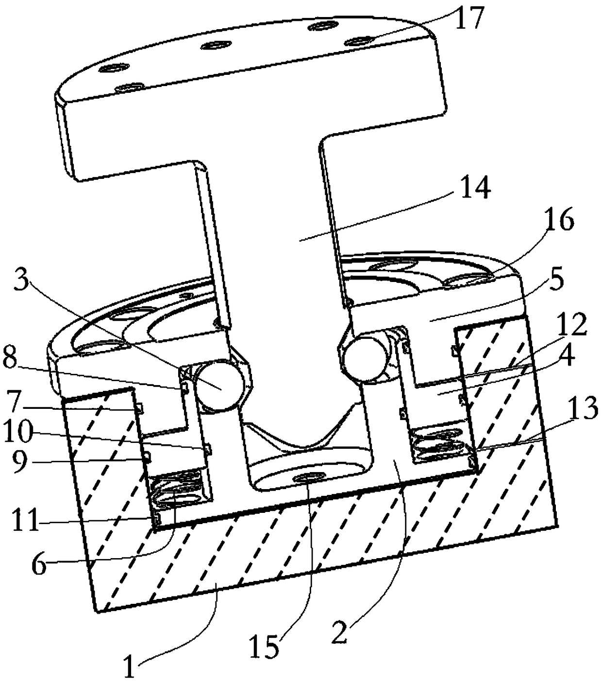
[0021] The specific implementation manner of the present invention will be described in more detail below with reference to schematic diagrams. Advantages and features of the present invention will be apparent from the following description and claims. It should be noted that all the drawings are in a very simplified form and use imprecise scales, and are only used to facilitate and clearly assist the purpose of illustrating the embodiments of the present invention.

[0022] After the inventor studied the existing pneumatic tooling fixtures, he found that:

[0023] (1) Most of the current pneumatic fixtures adopt mechanical locking methods, such as general piston gravity locking or spring mechanical locking. The locking process does not require or only needs short-term pneumatic pressure, mainly relying on the force of the piston. The gravity and the thrust of the compression spring work together to squeeze and push the steel ball and then lock it. During the locking process,...


PUM


Abstract

The invention provides a quick clamping system. The quick clamping system comprises a baseplate cavity, a clamping device and a pneumatic device, wherein the top surface of the baseplate cavity is opened; the clamping device is mounted in the baseplate cavity and comprises a base shell, steel balls, a piston and a body; the baseplate cavity, the base shell, the piston and the body fit one anotherin a sealing manner to form two airtight chambers being variable in volume; the piston can be driven by an external pneumatic pressure power to move up and down in the axial direction of the base shell, so as to squeeze or loosen the steel balls at the top of the base shell to achieve a locking or unlocking function; the pneumatic device is used for driving the piston and comprises gas paths and an external gas source; the gas paths are connected with the two airtight chambers. The quick clamping system provided by the invention can effectively solve the problems of a pneumatic clamping device: piston wearing and getting stuck as well as instability or even loss of the clamping function and further improves the locking / unlocking speed when compared to the pneumatic clamping device.

Description

technical field [0001] The invention relates to the field of precision machining machinery manufacturing, in particular to a quick clamping system. Background technique [0002] With the vigorous development of mechanical processing and manufacturing industry, the precision and production efficiency of processing parts are required to be higher and higher, and there are more and more forms of process concentration, one person with multiple machines, and one machine with multiple parts. Then the requirements for fixtures are getting higher and higher, and the standardization and automation of fixtures is imminent. In order to meet the above-mentioned production needs, two kinds of more advanced tooling fixtures, hydraulic and pneumatic, have appeared, which have changed the traditional manual clamping and adjustment positioning methods, effectively improved the machining accuracy, shortened the clamping adjustment time, and the production efficiency has also increased. The i...

Claims


Application Information

Patent Timeline
Patent Type & Authority Applications(China)
IPC IPC(8): B23Q3/08
CPCB23Q3/08
Inventor 徐仁科
Owner SHANGHAI DINGXIN ELECTROMECHANICAL EQUIP
Learn More