Computer hardware transporting device

A technology of computer hardware and transportation devices, which is applied in the field of computer hardware transportation devices, and can solve problems such as severe vibration, damage, and economic loss of computer hardware

Inactive Publication Date: 2017-08-18
黄思珍
View PDF8 Cites 6 Cited by
  • Summary
  • Abstract
  • Description
  • Claims
  • Application Information

AI Technical Summary

Problems solved by technology

[0003] At present, in the process of transporting computer hardware, due to encountering uneven ground during transportation, there will be great bumps, which will cause violent vibrations and damage to computer hardware, resulting in economic losses. Therefore, it is urgent to develop a Shock-absorbing function, it is not easy to generate vibration during transportation, it is not easy to be damaged, and it is a computer hardware transportation device that reduces economic losses

Method used


Image

  • Computer hardware transporting device
  • Computer hardware transporting device
  • Computer hardware transporting device

Examples


Embodiment 1

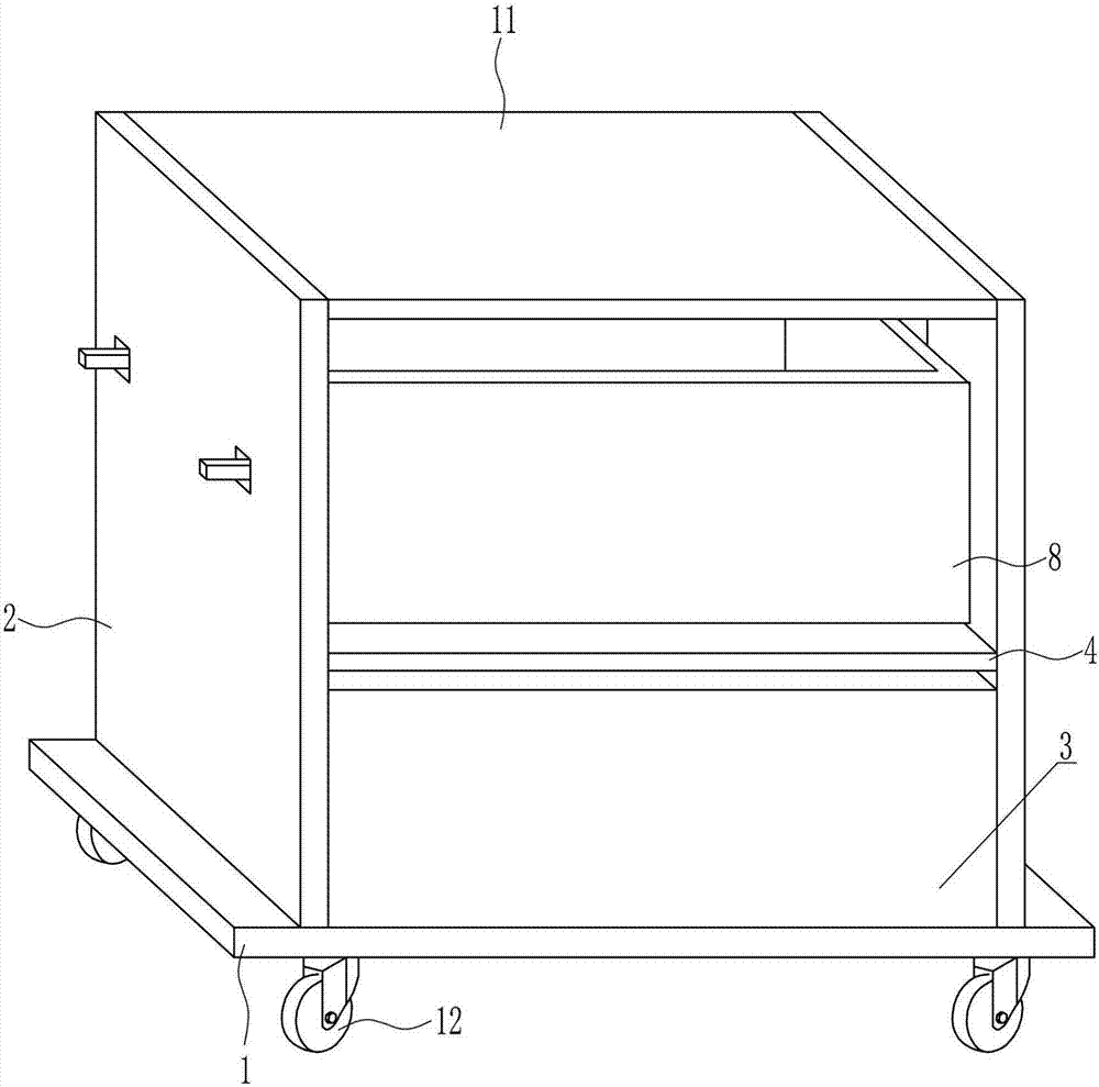
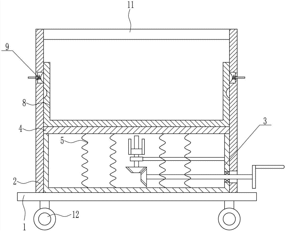
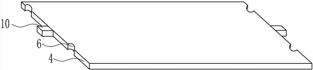
[0039] A computer hardware transport device such as Figure 1-10 As shown, it includes a bottom plate 1, a support plate 2, a lifting mechanism 3, a horizontal plate 4, a first spring 5, a storage box 8, a locking device 9, a slider 10, a top plate 11 and wheels 12, and the left and right sides of the top of the bottom plate 1 The support plate 2 is arranged symmetrically, and the support plate 2 is arranged vertically. The support plate 2 is connected to the top of the bottom plate 1 through bolt connection. The top of the bottom plate 1 between the two support plates 2 is provided with a lifting mechanism 3. A horizontal plate 4 is arranged above the lifting mechanism 3 in the room, and a first spring 5 is connected between the bottom of the horizontal plate 4 and the lifting mechanism 3. The top of the horizontal plate 4 is provided with a placement box 8, and the placement box 8 is open, and the placement box 8 Slidingly fit with the horizontal plate 4, the front and rear ...

Embodiment 2

[0041] A computer hardware transport device such as Figure 1-10 As shown, it includes a bottom plate 1, a support plate 2, a lifting mechanism 3, a horizontal plate 4, a first spring 5, a storage box 8, a locking device 9, a slider 10, a top plate 11 and wheels 12, and the left and right sides of the top of the bottom plate 1 The support plate 2 is arranged symmetrically, and the support plate 2 is arranged vertically. The support plate 2 is connected to the top of the bottom plate 1 through bolt connection. The top of the bottom plate 1 between the two support plates 2 is provided with a lifting mechanism 3. A horizontal plate 4 is arranged above the lifting mechanism 3 in the room, and a first spring 5 is connected between the bottom of the horizontal plate 4 and the lifting mechanism 3. The top of the horizontal plate 4 is provided with a placement box 8, and the placement box 8 is open, and the placement box 8 Slidingly fit with the horizontal plate 4, the front and rear ...

Embodiment 3

[0044] A computer hardware transport device such as Figure 1-10 As shown, it includes a bottom plate 1, a support plate 2, a lifting mechanism 3, a horizontal plate 4, a first spring 5, a storage box 8, a locking device 9, a slider 10, a top plate 11 and wheels 12, and the left and right sides of the top of the bottom plate 1 The support plate 2 is arranged symmetrically, and the support plate 2 is arranged vertically. The support plate 2 is connected to the top of the bottom plate 1 through bolt connection. The top of the bottom plate 1 between the two support plates 2 is provided with a lifting mechanism 3. A horizontal plate 4 is arranged above the lifting mechanism 3 in the room, and a first spring 5 is connected between the bottom of the horizontal plate 4 and the lifting mechanism 3. The top of the horizontal plate 4 is provided with a placement box 8, and the placement box 8 is open, and the placement box 8 Slidingly fit with the horizontal plate 4, the front and rear ...


PUM

PropertyMeasurementUnit
Thicknessaaaaaaaaaa

Abstract

The invention relates to a hardware transporting device, in particular to a computer hardware transporting device. The computer hardware transporting device aims to achieve the technical effects of having the damping function, being not prone to generating shake and not prone to causing damage in the transportation process and reducing the economic loss. The computer hardware transporting device comprises a base plate, two support plates, a lifting mechanism, a cross plate, first springs, a holding box, a locking device and the like. The two support plates are symmetrically and vertically arranged on the left side and the right side of the top of the base plate. The support plates are connected with the top of the base plate in a bolted manner. The portion, between the two support plates, of the top of the base plate is provided with the lifting mechanism. The cross plate is arranged above the lifting mechanism located between the two support plates. The first springs are connected between the bottom of the cross plate and the lifting mechanism. The computer hardware transporting device achieves the effects of having the damping function, being not prone to generating shake and not prone to causing damage in the transportation process and reducing the economic loss.

Description

technical field [0001] The invention relates to a hardware transportation device, in particular to a computer hardware transportation device. Background technique [0002] Computer hardware: refers to the general term for various physical devices composed of electronic, mechanical and optoelectronic components in a computer system. These physical devices form an organic whole according to the requirements of the system structure to provide a material basis for the operation of computer software. In short, the function of computer hardware is to input and store programs and data, and to execute programs to process data into a usable form. From the appearance point of view, the microcomputer is composed of the main chassis and external equipment. The main box mainly includes CPU, memory, main board, hard disk drive, optical drive, various expansion cards, connecting wires, power supply, etc.; external devices include mouse, keyboard, etc. [0003] At present, in the process...

Claims


Application Information

Patent Timeline
IPC IPC(8): B65D81/05
CPCB65D81/05
Inventor 黄思珍
Owner 黄思珍
Why Eureka
Try Eureka