Fuel supply device for internal combustion engine and control device for fuel supply device

A fuel supply device and fuel technology, applied in the direction of fuel injection devices, fuel injection control, special fuel injection devices, etc., can solve the driver's harsh hearing problems, achieve load reduction, improve startability, and suppress abnormal sounds Effect

Inactive Publication Date: 2013-02-06
BOSCH CORP
View PDF2 Cites 0 Cited by
  • Summary
  • Abstract
  • Description
  • Claims
  • Application Information

AI Technical Summary

Problems solved by technology

In this way, there may be abnormal noises that are thought to originate from the relationship between the vibration of valves and piping, the effective flow path area of ​​the flow path through which the fuel passes, and the internal pressure, and the driver may also have a may be harshly heard

Method used


Image

  • Fuel supply device for internal combustion engine and control device for fuel supply device
  • Fuel supply device for internal combustion engine and control device for fuel supply device
  • Fuel supply device for internal combustion engine and control device for fuel supply device

Examples


no. 1 Embodiment approach

[0041] 1. The overall structure of the fuel supply device of the internal combustion engine

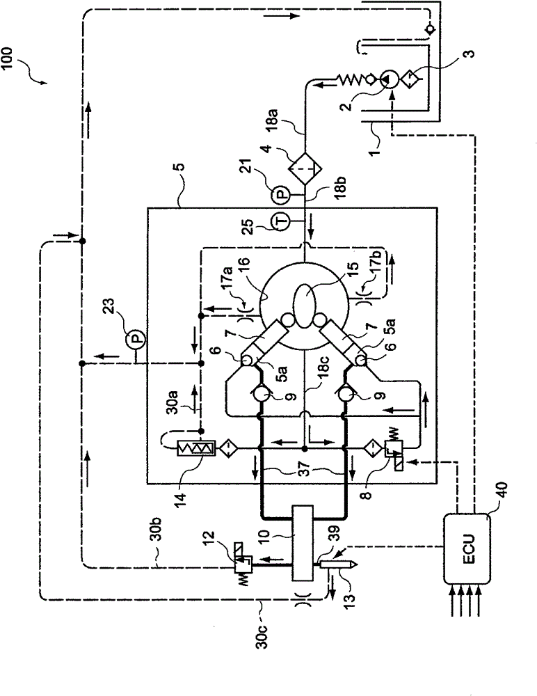
[0042] figure 1 A schematic configuration of a fuel supply device 100 for an internal combustion engine according to the present embodiment including a control unit (hereinafter referred to as "ECU": Electronic Control Unit) 40 of the fuel supply device according to the first embodiment of the present invention is shown.

[0043] figure 1 The fuel supply device 100 shown in is a fuel supply device 100 for a diesel engine, and includes a fuel tank 1, an electromagnetic low-pressure pump 2, a high-pressure pump 5, a common rail 10, and a fuel injection valve 13 as main components. Each component is connected by a fuel passage, in figure 1 Among them, the high-pressure fuel passage 37 is shown by a thick line, the low-pressure fuel passages 18a to 18c are shown by a thin line, and the fuel return paths 30a to 30c are shown by a dotted line.

[0044] The electromagnetic low-pressure...

specific example 1

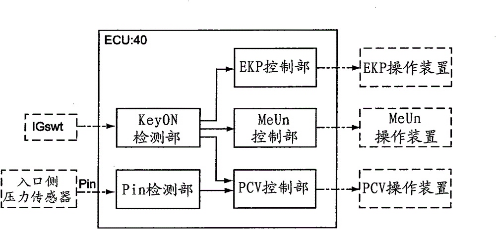
[0071] Below, based on Figure 4 flow chart and Figure 5 The timing diagram for the image 3 An example of the pre-start control of the internal combustion engine performed by the shown ECU 40 will be specifically described.

[0072] First, in step S1, it is detected that the ignition switch is turned on while the internal combustion engine is stopped ( Figure 5 in t1). As described above, in this step S1 , instead of detecting that the ignition switch is turned on, it is also possible to detect that the operation switch for the pre-start control of the internal combustion engine is turned on.

[0073] When it is detected that the ignition switch is turned on in step S1, in step 2, the flow control valve MeUn is fully open, while the pressure control valve PCV is fully closed ( Figure 5 in t2). In this embodiment, the flow control valve MeUn and the pressure control valve PCV of the normally open type are used. Since the flow control valve MeUn and the pressure control...

specific example 2

[0082] In the specific example 1 described above, the control of the pressure control valve PCV is started when the inlet pressure Pin of the high-pressure pump exceeds the reference value Pin0, but as shown in the following specific example 2, it can also be set to a preset value. The control of the pressure control valve PCV is started at the timing of the elapse of the reference time from the reference value of the elapsed time after the start of driving the electromagnetic low-pressure pump EKP.

[0083] Figure 7 and Figure 8 A flowchart and a sequence chart for explaining specific example 2 of this embodiment are shown.

[0084] First, as in steps S1 and S2 in the above-mentioned specific example 1, when it is detected in step S11 that the ignition switch is turned on ( Figure 8 In t11), in step S12, the flow control valve MeUn is fully open, while the pressure control valve PCV is fully closed ( Figure 8 in t12).

[0085]Next, in step S13, the drive of the electr...


PUM


Abstract

A fuel supply apparatus of an internal combustion engine is provided which can discharge air bubbles or air from within fuel supply paths while increasing pressure within a common rail up to a predetermined pressure level before a start of the internal combustion engine, can reduce a period of time of cranking from when an ignition switch is switched on and which can reduce noise that occurs when the air bubbles or air are being discharged. The fuel supply apparatus is provided with a flow rate control valve that adjusts a flow rate of fuel supplied to the common rail and a pressure control valve that reduces the pressure within the common rail. The fuel supply apparatus is further provided with: a pre-start drive control portion that performs a pre-start drive of an electromagnetic low pressure pump before the start of the internal combustion engine; a flow rate control valve control portion that maintains the flow rate control valve in an open state while the pre-start drive is being performed; and a pressure control valve control portion that maintains the pressure control valve in a closed state and performs a control that opens the pressure control valve at least once for a short time period while the pre-start drive is being performed.

Description

technical field [0001] The invention relates to a fuel supply device for an internal combustion engine and a control device for the fuel supply device. In particular, it relates to a fuel supply device for an internal combustion engine and a control device for the fuel supply device, which drive a low-pressure pump before starting the internal combustion engine. Background technique [0002] Conventionally, as a device for supplying fuel to an internal combustion engine including a diesel engine, an accumulator-type fuel supply device (common rail system) is used. In the common rail, by supplying the normally high-pressure fuel to each fuel injection valve, it is possible to perform compact fuel injection by energization control of the fuel injection valve. [0003] Such an accumulator-type fuel supply device includes a fuel tank, a low-pressure pump, a high-pressure pump, a common rail, and a fuel injection valve. Furthermore, the fuel in the fuel tank is sucked up by the...

Claims


Application Information

Patent Timeline
Patent Type & Authority Patents(China)
IPC IPC(8): F02D41/06F02M59/20F02M55/00F02M55/02
CPCF02M63/025F02D41/3863F02M59/06F02D2200/0606F02M59/102F02D2250/02F02M2200/60F02D41/06F02D2200/0602F02M63/0265
Inventor 松木宏金子博隆吉田宗之
Owner BOSCH CORP
Why Eureka
Try Eureka