Motor, motor device and pointer display device

A motor and rotor technology, applied in the field of pointer display devices, can solve problems such as rotor vibration and bearing life reduction

Inactive Publication Date: 2018-05-15
SANKYO SEIKI MFG CO LTD
View PDF10 Cites 0 Cited by
  • Summary
  • Abstract
  • Description
  • Claims
  • Application Information

AI Technical Summary

Problems solved by technology

Therefore, the rotor vibrates, for example, causing abnormal noise and shortening of bearing life.

Method used


Image

  • Motor, motor device and pointer display device
  • Motor, motor device and pointer display device
  • Motor, motor device and pointer display device

Examples


Embodiment approach 1

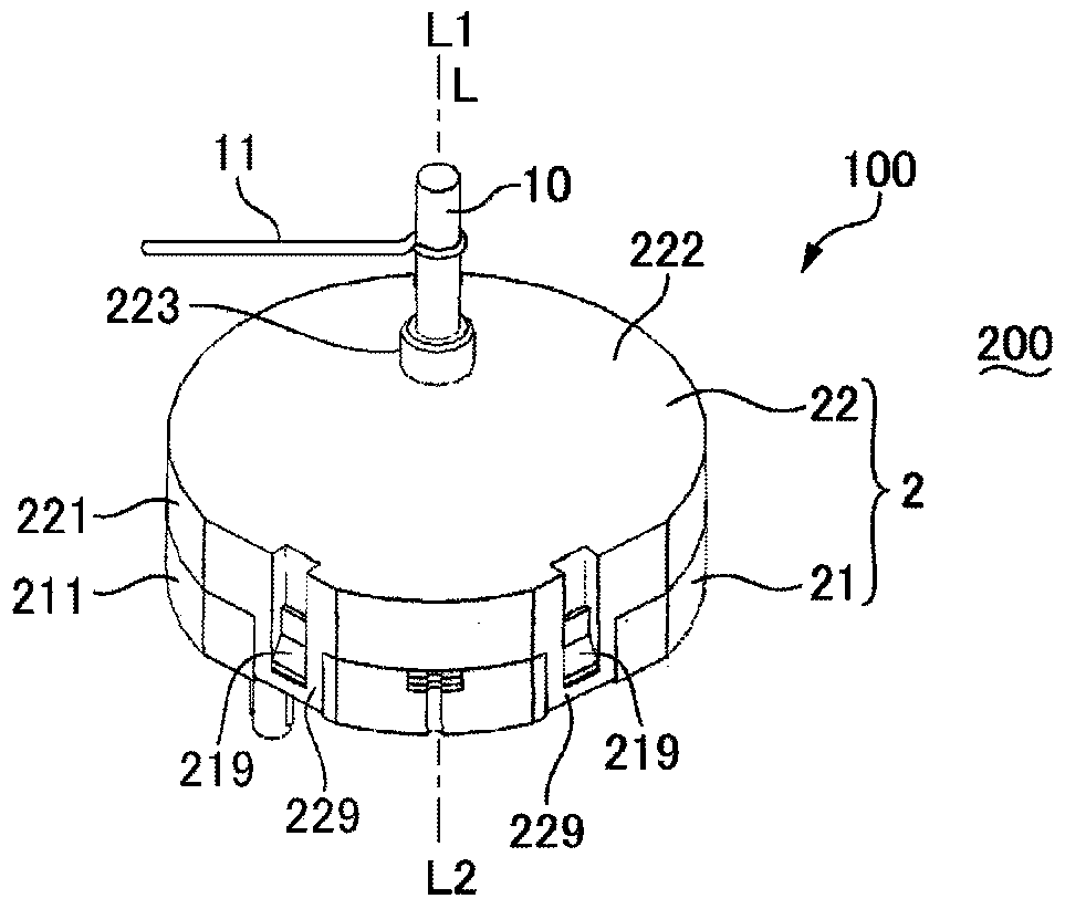
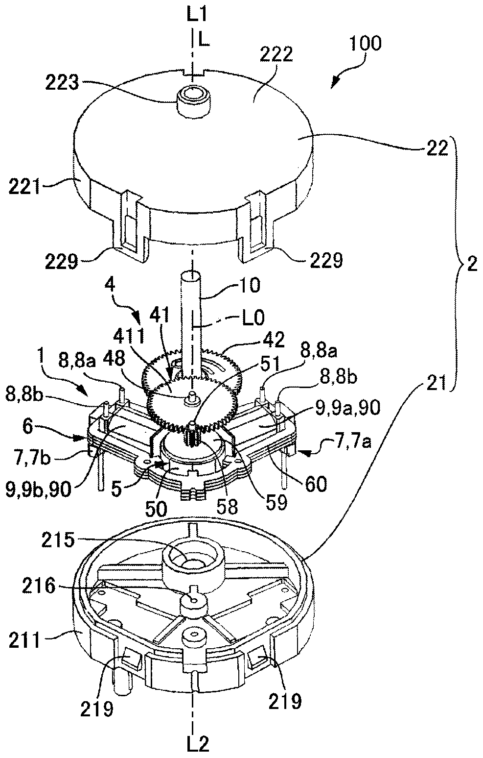
[0052] (The overall structure of the motor unit)

[0053] 1( a ) and FIG. 1( b ) are explanatory diagrams of the motor device 100 according to Embodiment 1 of the present invention, and FIG. 1( a ) is a view of the motor device 100 viewed from the side where the output shaft 10 protrudes. Perspective view, FIG. 1( b ) is an exploded view of the motor device 100 viewed from the side where the output shaft 10 protrudes. In the following description, the protruding side of the output shaft 10 in the direction in which the axis L of the output shaft 10 extends is defined as one side L1 , and the side opposite to the protruding side of the output shaft 10 is defined as the other side L2 . Also, let the axis of the rotor 5 of the motor 1 be the rotation center axis L0. In addition, for convenience, one side of the rotation center axis L0 is also referred to as one side L1, and the other side of the rotation center axis L0 is also described as the other side L2.

[0054] The motor ...

Embodiment approach 2

[0095] Figure 6 It is an explanatory diagram schematically showing the air gap between the salient pole 61 of the motor 1 and the magnet 50 used in the motor device 100 according to Embodiment 2 of the present invention. 7(a) and 7(b) are explanatory views of the stator core 60 used in the motor 1 of the motor device 100 according to Embodiment 2 of the present invention, and FIG. 7(a) is a perspective view of the stator core 60. , FIG. 7(b) is an exploded view of the stator core 60. In addition, since the basic structure of this embodiment is the same as Embodiment 1, the same code|symbol is attached|subjected to the same part, and the description is abbreviate|omitted.

[0096] Such as Figure 6 As shown, the present embodiment is the same as Embodiment 1, and the structure of the air gap sandwiched between the end portions 610f, 610b of the main poles (salient poles 61f, 61b) and the outer peripheral surface of the magnet 50 is similar to that of the first auxiliary pole...

Embodiment approach 3

[0116] Figure 10 It is an explanatory diagram schematically showing the air gap between the salient pole 61 of the motor 1 and the magnet 50 used in the motor device 100 according to Embodiment 3 of the present invention. In addition, since the basic structure of this embodiment is the same as that of the embodiment, the same code|symbol is attached|subjected to the same part, and the description is abbreviate|omitted.

[0117] Such as Figure 10 As shown, in the present embodiment, S poles and N poles are alternately formed on the outer peripheral surface of the magnet 50 at equal angular intervals. In the present embodiment, five pairs of S poles and N poles are formed in the magnet 50 . Therefore, in the magnet 50, a total of ten N poles and S poles are formed at equal angular intervals, so that the angular positions of the adjacent S poles and N poles in the circumferential direction are shifted by 36°.

[0118] In the stator core 60 , three salient poles 61 are formed...


PUM


Abstract

The present invention provides a motor capable of suppressing radial vibration of a rotor, a motor device having the motor, and a pointer display device. In the motor, coils are respectively arranged around two salient poles (61f, 61b) (main poles) located in a first angular range (θ1) smaller than 180° among a plurality of salient poles of the stator core. And, the salient poles (61c to 61e) located in the second angle range (θ2) of 180° among the plurality of salient poles become the first auxiliary poles without coils arranged around them. The side opposite to the side where the two main poles (61f, 61b) are located is centered on the extension of an imaginary bisector that bisects the first angle range (θ1). The structure of the air gap between the main poles (61f, 61b) and the magnet is different from the structure of the air gap between the first auxiliary poles (61c to 61e) and the magnet.

Description

technical field [0001] The present invention relates to a motor, a motor device, and an analog display device in which coils are wound on two salient poles of a plurality of salient poles of a stator core provided along a peripheral surface of a magnet. Background technique [0002] A display device such as an automobile meter device adopts a structure in which a pointer is attached via a motor. On the other hand, a motor having a structure in which a plurality of salient poles of a stator core are arranged along a peripheral surface of a magnet and coils are wound on two of the plurality of salient poles has been proposed (see Patent Document 1). [0003] Patent Document 1: Japanese Patent Laid-Open No. 2005-333786 [0004] In the motor described in Patent Document 1, when the rotor rotates, forces act on the rotor from two radial directions perpendicular to the rotation center axis of the rotor. And, the force applied to the rotor from the radial direction is reversed al...

Claims


Application Information

Patent Timeline
Patent Type & Authority Patents(China)
IPC IPC(8): H02K37/16
Inventor 保科哲夫
Owner SANKYO SEIKI MFG CO LTD
Why Eureka
Try Eureka