
Wave energy and solar energy coupled iontophoresis power generation device and method

A power generation device and iontophoresis technology, applied in the field of wave energy and solar energy coupled iontophoresis power generation devices, can solve the problems of inability to provide ion electrolyte salinity gradient, scarcity, etc., achieve high-efficiency photoelectric electroosmosis energy conversion, simplify complex structure, the effect of improving energy conversion efficiency

Active Publication Date: 2020-08-11
XI AN JIAOTONG UNIV
View PDF4 Cites 5 Cited by
  • Summary
  • Abstract
  • Description
  • Claims
  • Application Information

AI Technical Summary

Benefits of technology

This technology uses waves or sunlights from different sources like wind turbines to generate electricity that helps move particles through membranes made up mostly of water molecules called hydrogel networks (Hydrogel). These charged droplets create tiny currents when they come close enough together. By doing this, these charges help transfer electrons between them - allowing atoms inside each particle to become mobile without being affected by gravity altogether. Consequently, it becomes possible to use sea ice ocean tides or other natural resources instead of burning coal, resulting in more sustainability and environmental benefits over conventional methods such as thermal nuclear reactor systems.

Problems solved by technology

Technological Problem: Current Solar Photovoltage (SPV) Power Generation System designs suffer from poor performance due to their complexity and limited space allocation capacity. Additionally, there is currently lack of efficient and stable sea waves energy harvesters suitable for island applications such as coastline fishery and offshore drilling platforms.

Method used


Image

  • Wave energy and solar energy coupled iontophoresis power generation device and method
  • Wave energy and solar energy coupled iontophoresis power generation device and method

Examples


Embodiment Construction

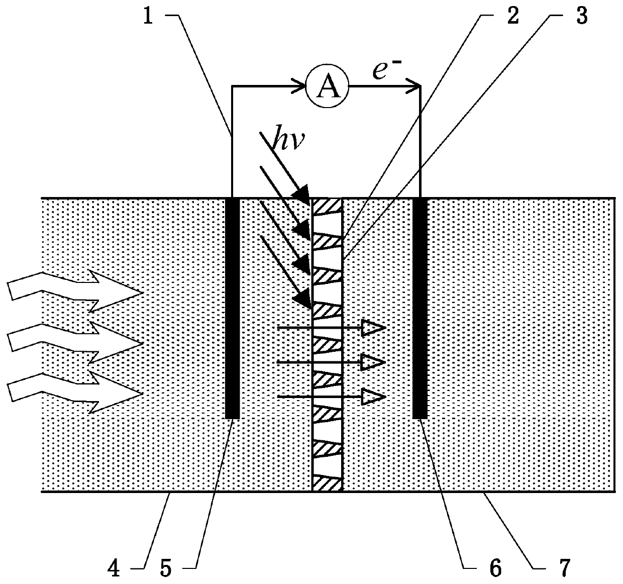
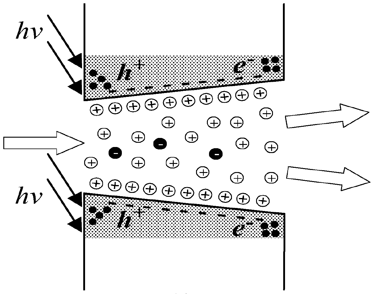
[0031] The following will refer to the attached figure 1 To attach figure 2 Specific examples of the present invention are described in more detail. Although specific embodiments of the invention are shown in the drawings, it should be understood that the invention may be embodied in various forms and is not limited to the embodiments set forth herein. Rather, these embodiments are provided for more thorough understanding of the present invention and to fully convey the scope of the present invention to those skilled in the art.

[0032] It should be noted that certain terms are used in the specification and claims to refer to specific components. Those skilled in the art should understand that they may use different terms to refer to the same component. The specification and claims do not use differences in nouns as a way of distinguishing components, but use differences in functions of components as a criterion for distinguishing. "Includes" or "comprises" mentioned thr...


PUM

PropertyMeasurementUnit
Thicknessaaaaaaaaaa

Abstract

The present invention discloses a wave energy and solar energy coupled iontophoresis power generation device and method. In the device, the top of a first chamber is a high-light-transmission wall surface, the side surface of the first chamber is in open communication with seawater, and the first chamber is provided with a first electrode immersed into the seawater; a second chamber comprises a closed lightproof wall surface and is provided with a second electrode immersed into seawater; an external circuit is connected with the first electrode and the second electrode; a composite nano-film capable of generating the photoelectric poising effect comprises a cation selective channel, a transmembrane potential difference is generated on the first side, close to the first chamber, of the composite nano-film through sunlight irradiation; and based on the pressure difference generated by the waves and the transmembrane potential difference, cations in the seawater directionally migrate fromthe first chamber to the second chamber through the cation selective channel to form ionic current, and electrons in an external circuit flow from the first electrode to the second electrode to formcurrent.

Description


Claims


Application Information

Patent Timeline
Owner XI AN JIAOTONG UNIV
Learn More