
Multifunctional valve assembly structure

A valve component and multi-functional technology, applied in the direction of functional valve types, valve details, diaphragm valves, etc., can solve problems such as troublesome after-sales maintenance, waste of social resources, complex structure, etc., to improve the stability of use and service life, and save manpower And the effect of simple structure of material and valve

Pending Publication Date: 2020-08-14
中山市佐恩斯电子科技有限公司
View PDF0 Cites 2 Cited by
  • Summary
  • Abstract
  • Description
  • Claims
  • Application Information

AI Technical Summary

Problems solved by technology

[0002] There are many types of gas and liquid valves on the existing market, and the structure is relatively complicated, especially the waterway control valve has water hammer (water hammer) during the valve closing process, which will cause great damage to the pipeline and produce annoying noise after long-term use
In some special cases, due to the large drop of high-rise buildings, siphons are prone to occur during the pipeline maintenance process, resulting in the siphoning of the pipelines connected to the toilets, which will return the sewage from the toilets to the drinking water pipelines, causing drinking water pollution
Due to the complex structure of most valves on the market, the large number of parts leads to an increase in material and production costs, which indirectly leads to a waste of social resources
[0003] In order to solve the siphon problem, the existing technology usually adds a one-way valve device at the water outlet position of the valve. This device not only has poor stability, but is prone to failure when impurities are stuck, resulting in larger product sizes, and also affects water quality. The flow rate cannot achieve the ideal flushing effect
[0004] Due to the structural defects of the traditional valve, the closing time of the valve is uncontrollable, and the ideal delayed closing time cannot be achieved, resulting in the need for high processing technology and cost in the production of the delayed valve
Due to the structural defects of the traditional valve, the pressure balance cavity of the valve will form a large pressure stretch and squeeze deformation on the diaphragm when the valve is closed. Because the diaphragm is not protected or supported, the diaphragm is stretched and squeezed infinitely, resulting in a The film is easy to tear or age, causing the product to need frequent maintenance or repair, which greatly wastes social resources such as manpower and material resources.
Due to the simple filter structure of traditional valves, the gas or liquid passage holes are easily blocked, and some valve control components or pressure relief components are blocked. The switch function and the water hole are blocked, which leads to the failure of the product function or the decrease of the flow rate, etc.
[0005] To sum up, due to the complex structure, many parts, high processing and production requirements, and large size of raw materials, traditional valves lead to difficult production, unstable product performance, short product life, large product size, troublesome after-sales maintenance, etc. Waste of social resources such as manpower and material resources

Method used


Image

  • Multifunctional valve assembly structure
  • Multifunctional valve assembly structure
  • Multifunctional valve assembly structure

Examples


Embodiment Construction

[0033] In order to make the technical means, creative features, goals and effects achieved by the present invention easy to understand, the present invention will be further described below in conjunction with specific embodiments.

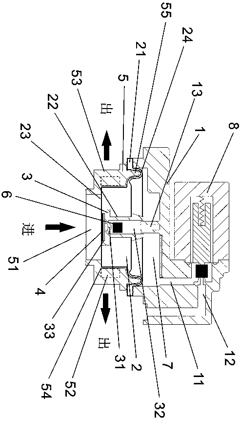
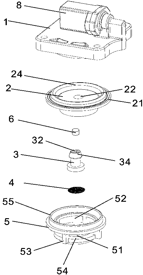
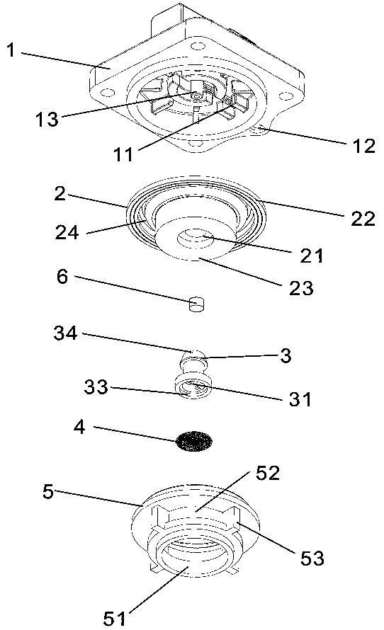
[0034] refer to Figure 1-3 , the specific embodiment adopts the following technical solutions: a multifunctional valve assembly structure, including a diaphragm cover 1, a diaphragm 2, a pilot assembly 3, a valve core filter device 4, a diaphragm protection bracket 5, a check device 6, a pressure The balance chamber 7 and the pressure relief control assembly 8, the diaphragm cover 1 is provided with a diaphragm cover pressure relief diversion hole 11, the diaphragm cover pressure relief diversion hole 11 and the matching pressure relief control assembly 8 The inlet gas or liquid inlet is connected, the pressure relief hole 12 of the pressure relief control assembly 8 is connected with the outlet 52 of the diaphragm protection bracket 5; the diaphra...


PUM


Abstract

The invention discloses a multifunctional valve assembly structure. A diaphragm cover, a diaphragm and a diaphragm protection support are matched to form a pressure balance cavity, so that the pressure in the direction of a gas inlet or a liquid inlet is kept balanced with the pressure balance cavity, and a valve is in a closed state; a pressure relief flow guide hole is formed in the diaphragm cover and communicates with a liquid inlet or a gas inlet of a pressure relief control assembly, so that the pressure relief control assembly releases the pressure of the pressure balance cavity betweenthe diaphragm cover and the diaphragm through a pressure relief switch of the pressure relief control assembly; due to the fact that the pressure in the direction of the gas inlet or the liquid inletis larger than the pressure of the pressure balance cavity, the diaphragm is pushed away towards the diaphragm cover, and the effect of opening the valve is achieved; the top of the diaphragm protection support supports the telescopic surface of the diaphragm, the diaphragm cannot be deformed and damaged due to pressure extrusion of the pressure balance cavity, and the service life of the diaphragm is greatly prolonged; and a non-return device is additionally arranged in a pilot assembly of the diaphragm, so that the problem of siphon backflow is solved.

Description

technical field [0001] The invention relates to the technical field of gas and liquid valve control structures, and in particular to a multifunctional valve assembly structure. Background technique [0002] There are many types of gas and liquid valves on the existing market, and the structure is more complicated. Especially, the waterway control valve has water hammer (water hammer) during the valve closing process. Long-term use will cause great damage to the pipeline and generate annoying noise. In some special cases, due to the large drop of high-rise buildings, siphons are prone to occur in the pipeline maintenance process, resulting in siphons in the pipelines connected to the toilets, which will return the sewage from the toilets to the drinking water pipelines, causing drinking water pollution. Because most of the valves on the market have complex structures and more parts, the cost of materials and production increases, which indirectly leads to the waste of social ...

Claims


Application Information

Patent Timeline
Patent Type & Authority Applications(China)
IPC IPC(8): F16K7/17F16K15/14F16K15/18F16K31/385F16K47/02B01D35/04
CPCB01D35/04F16K7/17F16K15/144F16K31/385F16K47/023F16K15/1825
Inventor 孔祥存李丽茵
Owner 中山市佐恩斯电子科技有限公司
Learn More