Ventilation detection equipment for underground dwelling houses

A technology for testing equipment and housing, applied in ventilation systems, lighting and heating equipment, space heating and ventilation, etc., can solve problems such as poor air quality, lack of cleaning mechanism, short circuit of wind suction equipment, etc., and achieve stable circulating airflow Effect

Active Publication Date: 2020-08-14
南通科创建设工程检测有限公司
View PDF4 Cites 2 Cited by
  • Summary
  • Abstract
  • Description
  • Claims
  • Application Information

AI Technical Summary

Problems solved by technology

[0002] Underground dwelling houses often appear in first-tier cities in my country. These houses are cheap and suitable for people with poor economic conditions. The disadvantages of these houses are that they are small and poorly ventilated, and they are prone to symptoms such as chest tightness and shortness of breath if they stay in the house for a long time. This kind of house is underground, and the air quality is poor, and the existing technology adopts intelligent ventilation equipment to deal with it
[0003] Most of the existing intelligent ventilation equipment is wind suction equipment. This kind of suction equipment relies on the rotation of the fan blades to disturb the airflow in the house and achieve the effect of ventilation. However, considering the particularity of underground dwelling houses, the underground is relatively humid and the air quality Poor, so this type of wind suction equipment is prone to short-circuit phenomenon, and its own lack of cleaning mechanism, resulting in poor ventilation effect after the equipment works for a period of time, so a kind of underground dwelling help ventilation detection equipment came into being

Method used


Image

  • Ventilation detection equipment for underground dwelling houses
  • Ventilation detection equipment for underground dwelling houses
  • Ventilation detection equipment for underground dwelling houses

Examples


Embodiment Construction

[0023] The following will clearly and completely describe the technical solutions in the embodiments of the present invention with reference to the accompanying drawings in the embodiments of the present invention. Obviously, the described embodiments are only some, not all, embodiments of the present invention. Based on the embodiments of the present invention, all other embodiments obtained by persons of ordinary skill in the art without making creative efforts belong to the protection scope of the present invention.

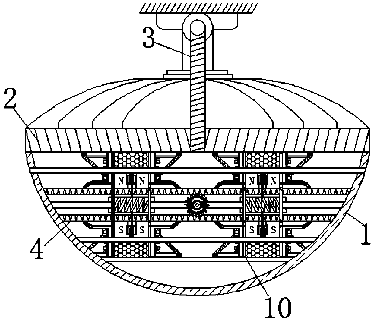
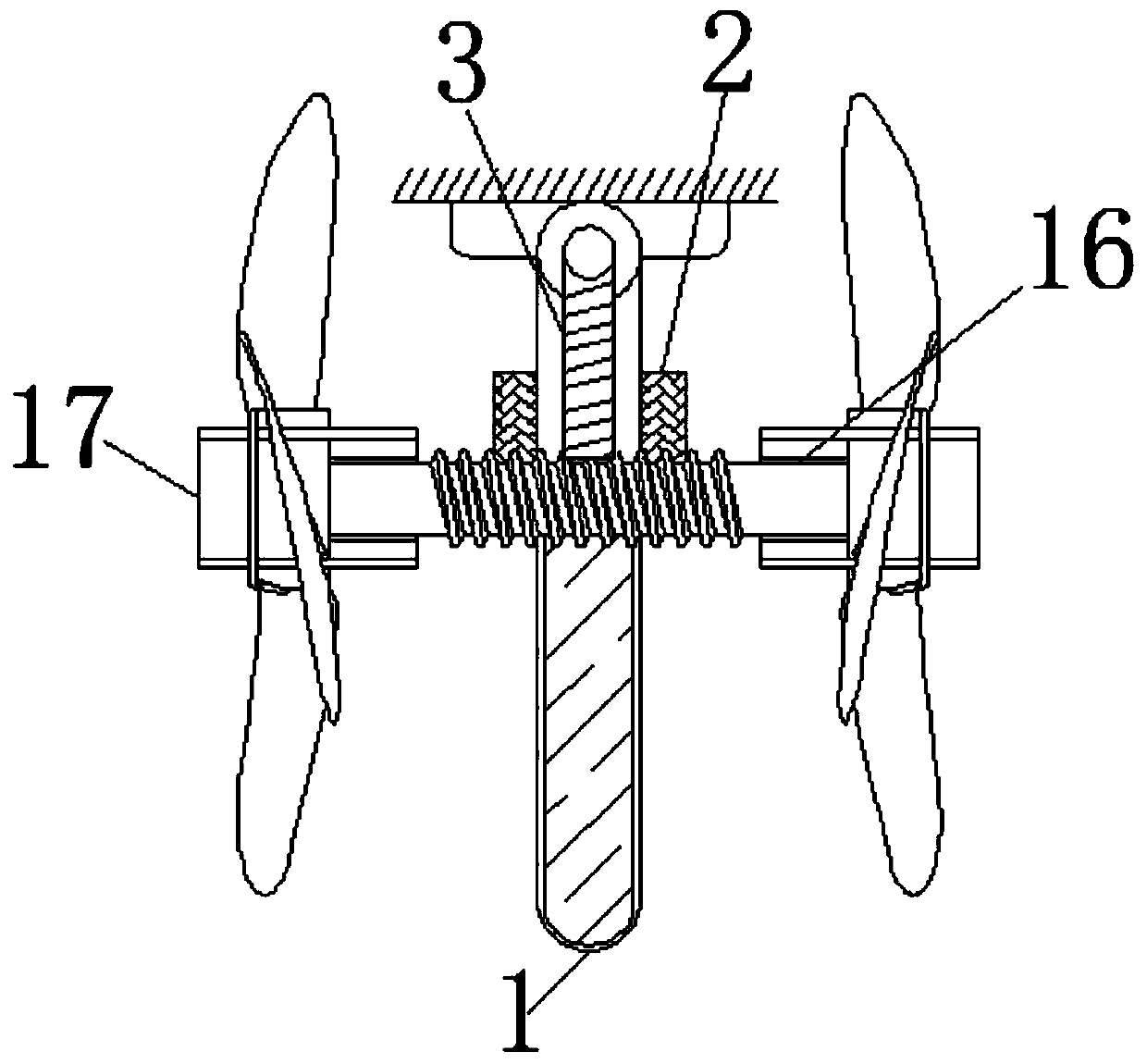
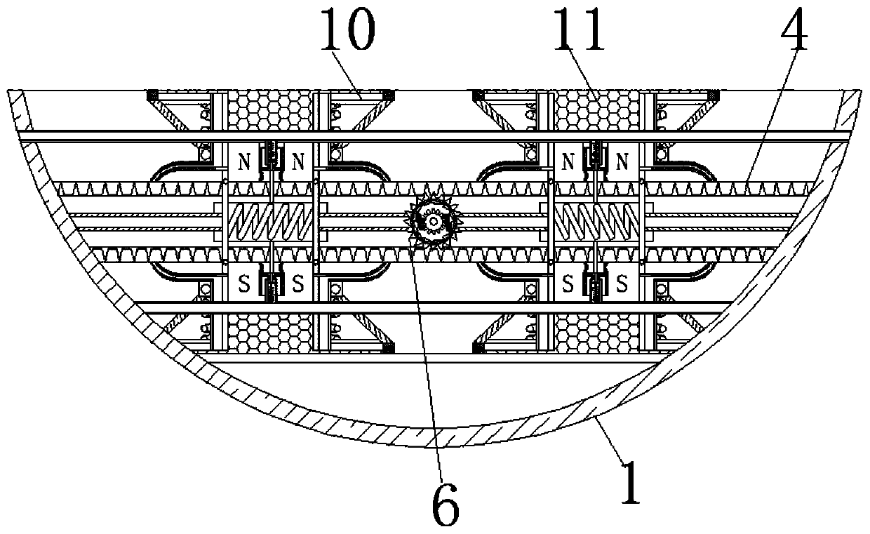
[0024] see Figure 1-7 , an underground dwelling aid ventilation detection device, comprising a housing 1, the top of the housing 1 is movably connected to a rotating shaft 2, the upper surface of the rotating shaft 2 is movably connected to a steering shaft 3, and the inside of the housing 1 is movably connected to a screw rod 4, The inside of screw rod 4 is fixedly connected with tooth plate 5, and the surface of tooth plate 5 is movably connected with gear ...


PUM


Abstract

The invention relates to the technical filed of household ventilation, and discloses ventilation detection equipment for underground dwelling houses. The ventilation detection equipment comprises a shell body, a rotating shaft is movably connected to the top of the shell body, a steering shaft is movably connected to the upper surface of the rotating shaft, a screw rod is movably connected to theinner part of the shell body, a tooth plate is fixedly connected to the inner part of the screw rod, a gear is movably connected to the surface of the tooth plate, a telescopic rod is movably connected to the surface of the gear, a reciprocating spring is movably connected to the end, away from the gear, of the telescopic rod, extrusion plates are correspondingly and movably connected to the two sides of the reciprocating spring, air bags are fixedly connected to the sides, away from a support frame, of the extrusion plates, and magnetic blocks are fixedly connected to the bottoms of the air bags. The reciprocating spring moves to cut magnetic induction lines generated by the magnetic blocks, thus an induced current is generated and can be used as force fordriving the gear to rotate, thatis, mutual reinforcing is achieved, the rotation of air change blades can achieve the function of air exchange, and thus the effect of driving air exchange by self amplification of wind power withoutan external power supply is achieved.

Description

technical field [0001] The invention relates to the technical field of household ventilation, in particular to an auxiliary ventilation detection device for underground dwelling houses. Background technique [0002] Underground dwelling houses often appear in first-tier cities in my country. These houses are cheap and suitable for people with poor economic conditions. The disadvantages of these houses are that they are small and poorly ventilated, and they are prone to symptoms such as chest tightness and shortness of breath if they stay in the house for a long time. This house is underground, and the air quality is relatively poor, and the prior art adopts intelligent ventilating equipment to handle this. [0003] Most of the existing intelligent ventilation equipment is wind suction equipment. This kind of suction equipment relies on the rotation of the fan blades to disturb the airflow in the house and achieve the effect of ventilation. However, considering the particulari...

Claims


Application Information

Patent Timeline
Patent Type & Authority Applications(China)
IPC IPC(8): F24F7/007H02K35/04B08B5/02
CPCB08B5/02F24F7/007H02K35/04
Inventor 王炜苏
Owner 南通科创建设工程检测有限公司
Why Eureka
Try Eureka