
LED display panel and LED display

A display panel and display backplane technology, which is applied in the fields of light emitting diode preparation and LED display preparation, can solve the problems of affecting display effect, dark lines on LED display panel, and inability to install LED chips on LED display panel, so as to improve display effect, Avoid dark streaks

Pending Publication Date: 2020-08-14
CHONGQING KONKA PHOTOELECTRIC TECH RES INST CO LTD
View PDF0 Cites 6 Cited by
  • Summary
  • Abstract
  • Description
  • Claims
  • Application Information

AI Technical Summary

Problems solved by technology

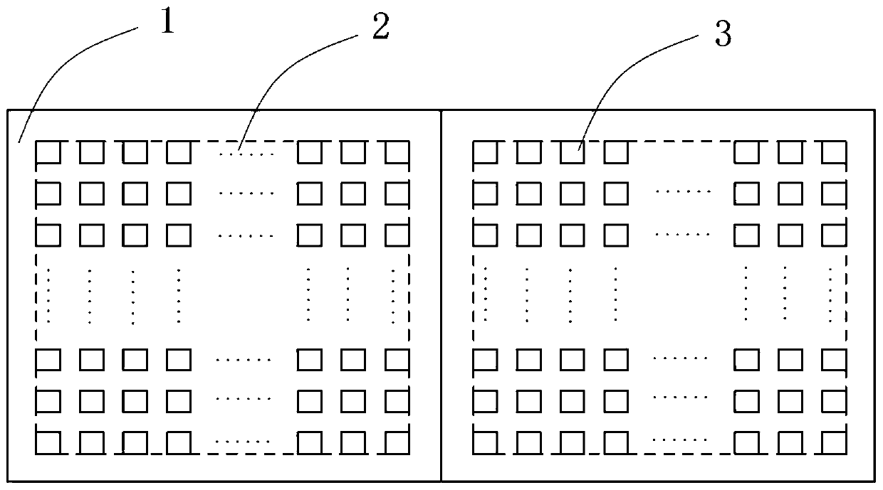
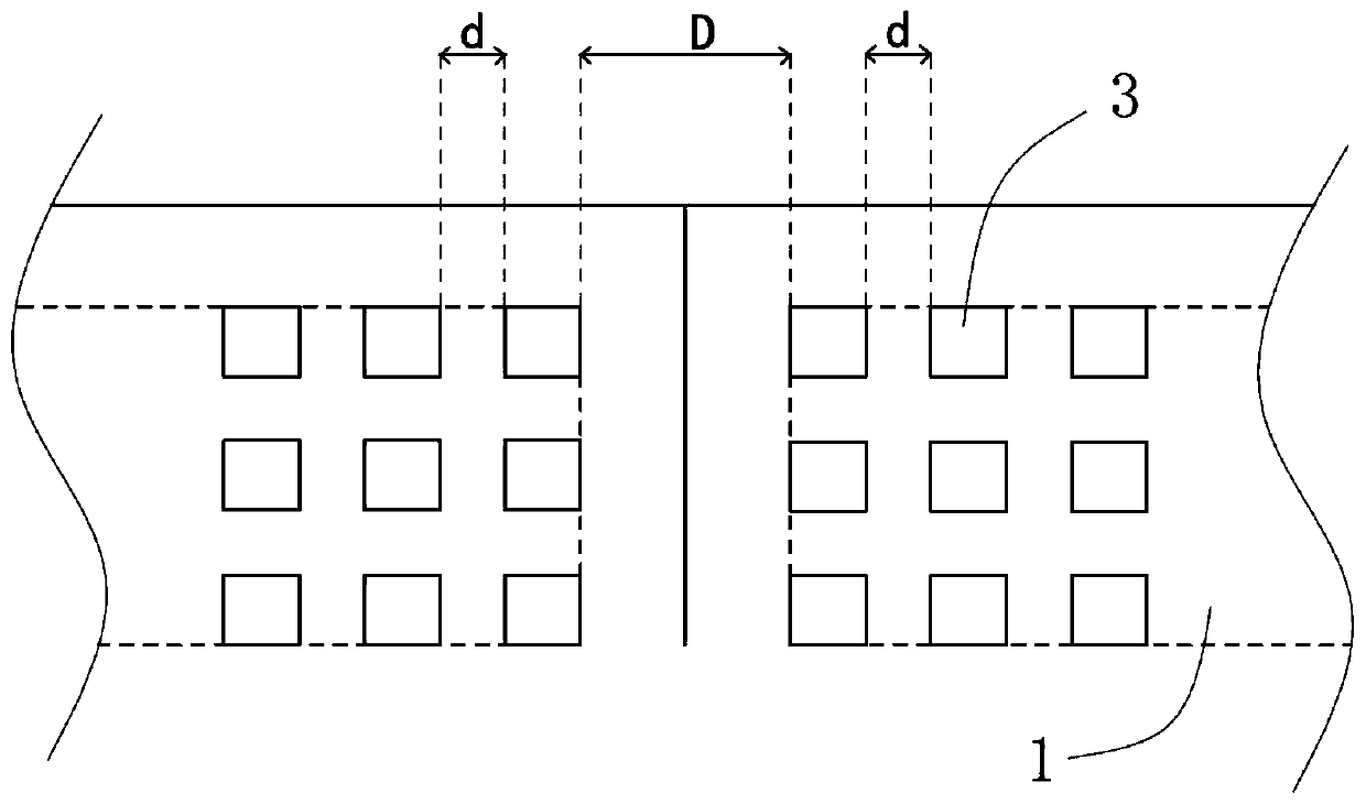
Due to the limited structure, LED chips cannot be placed on the edge of the LED display panel, but a certain blank area is left. When two adjacent LED display panels are spliced ​​together, this blank area will cause the adjacent LED display panel to display There will be visually dark lines between the panels, which will affect the overall display effect

Method used


Image

  • LED display panel and LED display
  • LED display panel and LED display
  • LED display panel and LED display

Examples


Embodiment Construction

[0063] In order to make the object, technical solution and advantages of the present invention more clear and definite, the present invention will be further described in detail below with reference to the accompanying drawings and examples. It should be understood that the specific embodiments described here are only used to explain the present invention, not to limit the present invention.

[0064] In the description of the present invention, it should be understood that the orientation or positional relationship indicated by the terms "center", "upper", "lower", "front", "rear", "left", "right" etc. are based on The orientations or positional relationships shown in the drawings are only for the convenience of describing the present invention and simplifying the description, and do not indicate or imply that the referred devices or components must have a specific orientation, be constructed and operated in a specific orientation, and therefore cannot be understood as Limitat...


PUM


Abstract

The invention provides an LED display panel and an LED display, the LED display panel comprises a display backboard provided with an LED array, and the LED array comprises LED chips arranged side by side; the LED chips comprise vertical emitting type light-emitting chips and inclined emitting type light-emitting chips. The vertical emitting type light-emitting chip is arranged in the LED array, and the orientation of main light emitted by the vertical emitting type light-emitting chip is perpendicular to the direction of the display backboard; the inclined emitting type light-emitting chip isarranged in the edge of the LED array , and main light emitted by the inclined emitting type light-emitting chip faces the direction far away from the geometric center of the display backboard. The vertical emitting type light-emitting chip is arranged in the LED array; the inclined emergent light-emitting chip is arranged in the edge of the LED array, the main light rays which are emitted by theinclined emitting type light-emitting chips and face the direction far away from the geometric center of the display back plate form a light condensation effect between the adjacent LED display panels, so that dark fringes are prevented from being generated between the adjacent LED display panels, and the overall display effect is improved.

Description

technical field [0001] The invention relates to the technical field of light-emitting diode preparation and LED display screen preparation, relates to an LED display panel and an LED display, and in particular to an LED display panel and an LED display capable of eliminating dark lines. Background technique [0002] LED, that is, light-emitting diode, emits energy through the recombination of electrons and holes, and can efficiently convert electrical energy into light energy. It has multiple advantages such as small size, rich colors, low energy consumption, and long service life. New solid-state light sources for general lighting. LED displays based on LEDs have many advantages such as high stability, long service life, and low operating temperature. At the same time, they also inherit the advantages of LEDs such as low power consumption, color saturation, fast response, and strong contrast. Application prospects. [0003] Generally, an LED display is formed by splicing ...

Claims


Application Information

Patent Timeline
Patent Type & Authority Applications(China)
IPC IPC(8): H01L27/15H01L33/20G09F9/33
CPCG09F9/33H01L27/156H01L33/20
Inventor 江仁杰徐瑞林钟光韦张嘉修苏财钰
Owner CHONGQING KONKA PHOTOELECTRIC TECH RES INST CO LTD
Learn More