
Adjusting valve

A technology for regulating valves and valve bodies, applied in the field of regulating valves, which can solve the problems of valve leakage, unstable operation, and short service life, and achieve the effects of avoiding pressure loss, avoiding disc vibration, and improving service life

Pending Publication Date: 2020-08-25
HANGZHOU WORLDWISE VALVE
View PDF10 Cites 0 Cited by
  • Summary
  • Abstract
  • Description
  • Claims
  • Application Information

AI Technical Summary

Problems solved by technology

[0003] The traditional regulating valve is just a simple valve disc and valve stem structure, the valve rod connects the valve disc and provides the opening and closing force for the operation of the valve disc, but due to the action of the medium force, the closing force of the valve disc pushing down is relatively large, The opening force of the Kai is small, resulting in unstable operation
In order to solve this problem, a balance hole channel is set on the valve disc to connect the space divided by the valve disc, so that part of the medium can flow through the balance hole channel, which balances the medium force and reduces the opening and closing force of the valve disc. However, due to the existence of the balance hole channel, the medium will flow out from the balance hole channel. When the balance medium force is not needed, the medium will still leak, resulting in a loss of pressure. At the same time, when the valve is opened and closed, the flow rate increases instantaneously. Large, the impact on the sealing surface is extremely large, the erosion is very serious and the valve core is damaged, the service life is short, and it is easy to cause the valve to leak

Method used


Image

  • Adjusting valve
  • Adjusting valve
  • Adjusting valve

Examples


Embodiment Construction

[0041] The present invention will be described in detail below in conjunction with the drawings and specific embodiments. It should be noted that in the drawings or descriptions, similar or identical parts use the same figure numbers, and implementations that are not shown or described in the drawings The method is a form known to those of ordinary skill in the art. In addition, the directional terms mentioned in the embodiments, such as "upper", "lower", "top", "bottom", "left", "right", "front", "rear", etc., are only for reference to the accompanying drawings. The directions are not intended to limit the protection scope of the present invention.

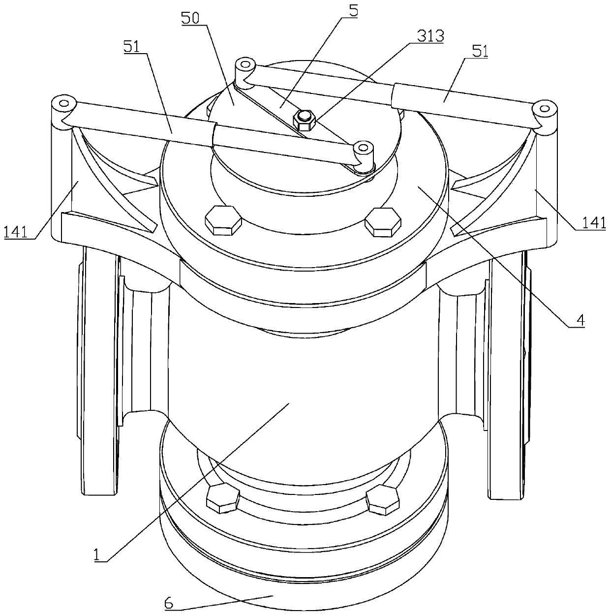
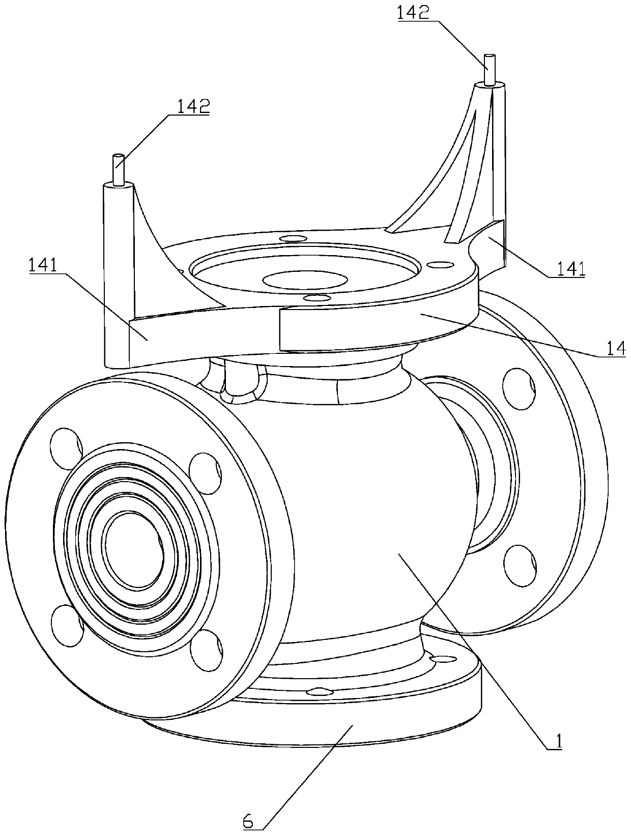
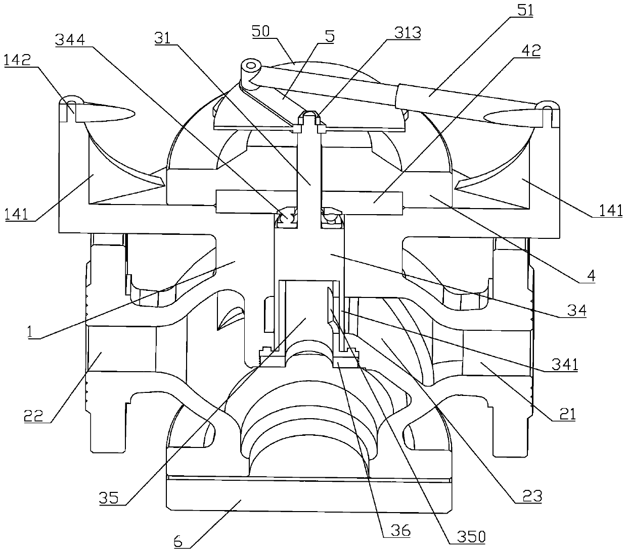
[0042] Such as Figure 1 to Figure 11As shown, a regulating valve of this embodiment includes a valve body 1, a valve core 31 and a valve cover 4, the valve cover 4 is fixedly installed on the valve body 1, and the valve body 1 is provided with an air inlet 21 and an exhaust port. 22. The valve body 1 includes an upper valve ca...


PUM


Abstract

The invention belongs to the technical field of valve equipment, and particularly relates to an adjusting valve. A valve body, a valve element and a valve cover are included. The center axis of a first communication hole and the center axis of a second communication hole are collinear. An upper valve cavity and a lower valve cavity are in communication through the first communication hole. A valveclack is arranged at the bottom end of the valve element and comprises a valve clack column and a valve clack barrel fixedly arranged on the valve clack column. The valve element penetrates through alimiting plate, the valve element is in clearance fit with the limiting plate, the top end of the valve element penetrates through the valve cover and is fixedly provided with a connecting rod, two hydraulic cylinders are further hinged to the valve body and are in center symmetry with the center axis of the valve element as the middle point, and each of the two ends of the connecting rod is hinged to one hydraulic cylinder. According to the purpose, the adjusting valve is provided, by means of the adjusting valve, influences on opening and closing force from medium force can be avoided, valve opening and closing are convenient, and pressure losses are avoided; and an inner barrel is used for replacing the valve clack to bear impact force on the valve clack barrel from high-pressure gas generated due to instant opening of the valve, and the service life of the valve clack barrel can be better prolonged.

Description

technical field [0001] The invention belongs to the technical field of valve equipment, and in particular relates to a regulating valve. Background technique [0002] Control valve, also known as control valve, in the field of industrial automation process control, is the final control element that changes the process parameters such as medium flow, pressure, temperature, liquid level, etc. by means of power operation by receiving the control signal output by the adjustment control unit. [0003] The traditional regulating valve is just a simple valve disc and valve stem structure, the valve rod connects the valve disc and provides the opening and closing force for the operation of the valve disc, but due to the action of the medium force, the closing force of the valve disc pushing down is relatively large, The opening force of the valve is small, resulting in unstable operation. In order to solve this problem, a balance hole channel is set on the valve disc to connect the...

Claims


Application Information

Patent Timeline
Patent Type & Authority Applications(China)
IPC IPC(8): F16K5/04F16K5/08F16K27/06F16K31/46F16K31/12F16K47/04F16K47/02
CPCF16K5/0407F16K5/0442F16K5/08F16K27/065F16K31/46F16K31/12F16K47/045F16K47/02
Inventor 陈立龙陈卫平张明谢小白
Owner HANGZHOU WORLDWISE VALVE
Learn More