Gasket retention system

一种保持系统、衬垫的技术,应用在衬垫领域,能够解决重新组装困难、系统不理想、耗时等问题

Active Publication Date: 2020-08-25
SPX FLOW INC
View PDF8 Cites 1 Cited by
  • Summary
  • Abstract
  • Description
  • Claims
  • Application Information

AI Technical Summary

Problems solved by technology

If during disassembly, the liner comes off the plate, reassembly is more difficult and time consuming
Although various conventional liner retention systems have been proposed, these systems are not ideal for various reasons

Method used


Image

  • Gasket retention system
  • Gasket retention system
  • Gasket retention system

Examples


Embodiment Construction

[0024] In the following, the present invention will be described in detail with reference to the accompanying drawings, in which the same reference numerals denote the same components throughout. Embodiments according to the present application propose an improved pad retention system which improves retention of the pad within the panel. In this way, the disassembly and reassembly of the plate stack in a plate heat exchanger is improved and resistant to degradation caused by exposure to chemicals, extreme temperatures, UV light, etc. This improved liner also provides excellent sealing characteristics and high resistance to material fatigue. Furthermore, due to the improved retention, labor costs are reduced by the improved gasket retention system and thus the slippage of the gasket from the plate is reduced during inspection, disassembly and reassembly of the plate heat exchanger.

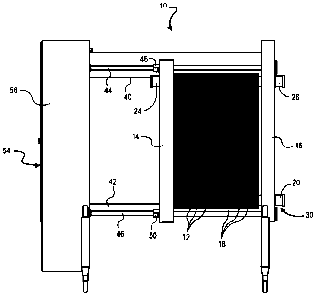
[0025] figure 1 is a side view of a plate heat exchanger 10 suitable for use with gaskets an...


PUM


Abstract

A gasket retention system includes a gasket and a plate. The gasket includes a loop. The loop includes a gasket tab extending from the gasket, a pair of loop arms flanking the gasket tab and extendingfrom the gasket, a loop webbing connecting the pair of loop arms, and a loop tab extending from the loop webbing toward the gasket tab. The plate includes a loop receiving seat. The loop receiving seat includes a gasket seat, a gasket tab slot to receive the gasket tab, a loop tab channel to receive the loop tab, a pair of loop arm channels to receive the pair of loop arms, and an edge for the loop webbing to bear upon.

Description

[0001] priority [0002] This application claims priority to US Provisional Application No. 62 / 616,788, filed January 12, 2018, entitled "Pad Retention System," the entire disclosure of which is incorporated into this application. technical field [0003] The present invention generally relates to a liner. More particularly, the present invention relates to a gasket retention system for use in plate heat exchangers. Background technique [0004] Plate heat exchangers are known to provide efficient transfer of heat from one fluid to another in a relatively small volume. Typically, plate heat exchangers consist of a number of plates to a hundred or more plates stacked and sealed together. For example, relatively small plate heat exchangers are often permanently sealed together by brazing. Larger plate heat exchangers are more commonly sealed by pairs of gaskets positioned between the plates or pairs of plates. Since the gasket is placed around each plate and due to the nu...

Claims


Application Information

Patent Timeline
Patent Type & Authority Applications(China)
IPC IPC(8): F28F3/10F28F9/00
CPCF28D9/005F28D9/0093F28F3/083F28F3/10F28F2280/00F28F2230/00
Inventor 耶斯·汉森·彼得森本尼·科特-詹森
Owner SPX FLOW INC
Why Eureka
Try Eureka