
Multistage centrifugal fan bearing removal device and method

A technology of bearing removal device and centrifugal fan, applied in hand-held tools, manufacturing tools, etc., can solve problems such as difficulty in bearing removal, achieve the effects of improving removal efficiency, saving manpower, and ensuring reliability

Inactive Publication Date: 2020-08-28
GUANGDONG UNIV OF PETROCHEMICAL TECH
View PDF5 Cites 1 Cited by
  • Summary
  • Abstract
  • Description
  • Claims
  • Application Information

AI Technical Summary

Problems solved by technology

[0005] The purpose of the present invention is to provide a multistage centrifugal fan bearing dismounting device and method to solve the problem of difficult dismounting of multistage centrifugal fan bearings in the prior art

Method used


Image

  • Multistage centrifugal fan bearing removal device and method
  • Multistage centrifugal fan bearing removal device and method
  • Multistage centrifugal fan bearing removal device and method

Examples


Embodiment 1

[0045] A bearing dismounting device, comprising a dismounting main body 100 and a lifting device 200, the dismounting main body 100 is connected to the output end of the lifting device 200; The two ends of 120 are respectively connected with the first dismounting device 130 and the second dismounting device 140; The second gear 141 in the second removal device 140 is meshed; the driving gear 121 rotates to drive the first gear 131 and the second gear 141 to rotate, the first gear 131 rotates to drive its output end to work, and the second gear 141 rotates to drive its output end work. The device includes a first dismounting device 130 and a second dismounting device 140. When dismounting the bearing, the output end of the first dismounting device 130 and the output end of the second dismounting device 140 are connected to the bolts on the bearing seat, and the user operates The prime mover 120 can quickly disassemble the bolts on the bearing, and then disassemble the bearing,...

Embodiment 2

[0057] The present invention also includes a dismounting method for the multistage centrifugal fan bearing, which requires the use of the dismounting device in Embodiment 1, and the method includes the following steps:

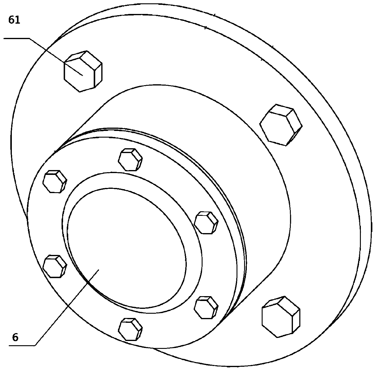
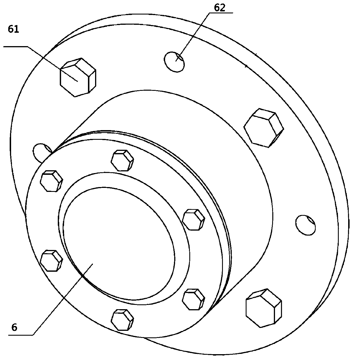
[0058] Step 1. On the front bearing seat 6, a screw hole 62 that runs through the front bearing seat is symmetrically provided, and a dismounting bolt is connected in the screw hole; screw hole, and a dismounting bolt is connected in the screw hole;

[0059] Step 2, disassemble the fastening bolts on the rear bearing seat 8, the removal of the fastening bolts specifically includes: the output end of the first dismounting device 130 and the output end of the second dismounting device 140 are connected with the fastening bolts on the rear bearing seat 8 To connect, the fastening bolts on the rear bearing seat are disassembled by the prime mover 120 . The output end of the first dismounting device 130 and the output end of the second dismounting device 140 are a...


PUM


Abstract

The invention discloses a multistage centrifugal fan bearing removal device and method. The device comprises a removal main body and a lifting device, wherein the removal main body is connected to theoutput end of the lifting device; the removal main body comprises a box body and a prime mover connected into the box body, and the two ends of the prime mover are connected with a first removal device and a second removal device correspondingly; a prime gear in the prime mover is meshed with a first gear in the first removal device, and the prime gear is meshed with a second gear in the second removal device; the prime gear rotates to drive the first gear and the second gear to rotate, the first gear rotates to drive the output end of the first gear to work, and the second gear rotates to drive the output end of the second gear to work. According to the device, bolts on a bearing seat can be rapidly removed, then a bearing is removed, so that the removal efficiency is improved, and manpower is saved.

Description

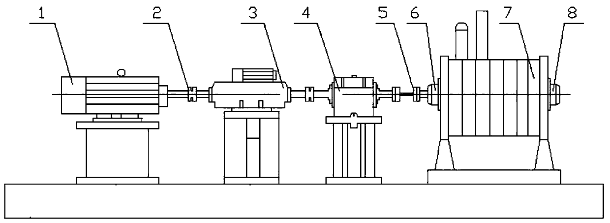
technical field [0001] The invention relates to the technical field of centrifugal fans, in particular to a bearing dismounting device and method for multistage centrifugal fans. Background technique [0002] With the continuous development of industrial technology, multi-stage centrifugal fans are more and more widely used in industry. At the same time, due to long-term operation, various failures will inevitably occur in the fan bearings. At this time, it needs to be disassembled for timely replacement and maintenance. The structure of multistage centrifugal fan is as follows: figure 1 As shown, the motor 1, the torque transmitter 3, the gearbox 4, and the multistage centrifugal fan 7 are all fixed on the base through the base. The multistage centrifugal fan 7 includes a front bearing seat 6 and a rear bearing seat 8 respectively, wherein the front bearing seat 6 is connected to the gearbox 4 through an adjustable coupling 5 . The structures of front bearing seat 6 and ...

Claims


Application Information

Patent Timeline
Patent Type & Authority Applications(China)
IPC IPC(8): B25B27/073
CPCB25B27/062
Inventor 林水泉张清华吕运容孙国玺段志宏朱冠华胡勤覃爱淞邵龙秋雷高伟
Owner GUANGDONG UNIV OF PETROCHEMICAL TECH
Learn More