Coiled tubing sand filling separate layer fracturing method

A technology of layered fracturing and tubing, which is applied in the direction of earthwork drilling, production fluid, wellbore/well components, etc., and can solve problems such as packers and failures that are prone to occur, so as to avoid failure problems, convenient operation and operability strong effect

Pending Publication Date: 2020-08-28
BC P INC CHINA NAT PETROLEUM CORP +1
View PDF7 Cites 0 Cited by
  • Summary
  • Abstract
  • Description
  • Claims
  • Application Information

AI Technical Summary

Problems solved by technology

[0003] The present invention provides a coiled tubing sand-packed layered fracturing method, which overcomes the deficiencies of the prior art and c

Method used


Image

  • Coiled tubing sand filling separate layer fracturing method
  • Coiled tubing sand filling separate layer fracturing method

Examples


Embodiment 1

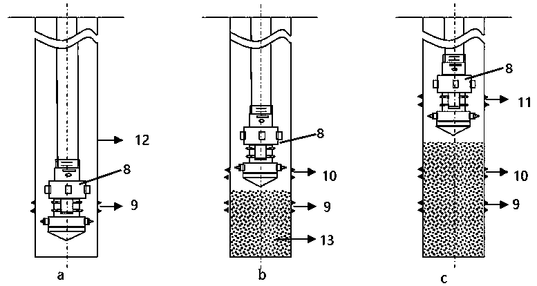
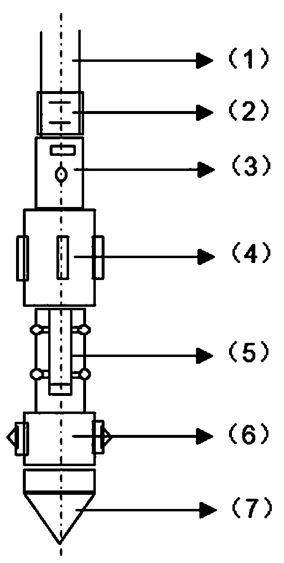
[0021] Embodiment 1: as attached Figures 1 to 2 As shown, the coiled tubing sand-packed layered fracturing method is carried out as follows: the first step is to determine the depth position of the perforation point: a fracturing tool string 8 is fixedly installed at the lower end of the coiled tubing 1, and the fracturing tool string 8 is formed by The connector 2, the motor head assembly 3, the centralizer 4, the injector 5, the positioner 6 and the guide shoe 7 are fixed and connected sequentially from top to bottom, and the fracturing tool string 8 is lowered to the determined perforation point depth position;

[0022] The second step, the first stage of perforation and fracturing: inject the sand-carrying fluid into the coiled tubing 1, and the sand-carrying fluid in the coiled tubing 1 passes through the injector 5 to blast and perforate the first layer of perforation. From the tubing 1 to the second-stage perforation point, the fracturing fluid and sand-carrying fluid...

Embodiment 2

[0033] Embodiment 2: As an optimization of the above embodiment, when the pressure test of the sand-packing section in the sand-packing layered fracturing process is unqualified, continue to fill or re-fill the sand until the pressure test requirements are met.

[0034] When the pressure test of the sand-packing section in the process of sand-packing layered fracturing fails, re-check the sand-packing volume, volume of the sand-packing section, and sand settlement time, and check the sand surface if necessary. If the sand surface does not reach the designed well depth, Continue sand filling. If the pressure test of the sand filling section is still unqualified, the sand filling and layering process can be carried out again.

Embodiment 3

[0035] Embodiment 3: As an optimization of the above embodiment, after the fracturing of all layers is completed, the fracturing tool string 8 under the coiled tubing 1 is replaced with a sand washing tool. The sand is filled and washed out of the wellbore. After the wellbore is cleaned, the coiled tubing 1 and the sand washing tool are put forward.


PUM


Abstract

The invention relates to the technical field of separate layer fracturing operation, in particular to a coiled tubing sand filling separate layer fracturing method. The method is carried out accordingto the following steps that 1, the depth position of a perforation point is determined; 2, primary perforation fracturing is carried out; 3, sand filling and layering are carried out; 4, separate layer fracturing is carried out; and 5, the operation methods from the second step to the fourth step are repeated to complete the perforating and fracturing procedures of remaining layers. Compared withan existing coiled tubing separate layer fracturing method, the sand filling separate layer fracturing method has the advantages that the modes such as a packer, a bridge plug, and a cement plug do not need to be used for achieving separate layer, and the sand filling method is used for achieving separate layer, and therefore a series of fault problems caused by using of the packer are avoided, separate layer fracturing can be safely and effectively achieved, and the method has the characteristics of being high in operability and convenient and quick in operation.

Description

technical field [0001] The invention relates to the technical field of layered fracturing operations, and relates to a sand-packed layered fracturing method for coiled tubing. Background technique [0002] With the promotion and popularization of downhole operation technology of coiled tubing, more and more coiled tubing has been used in downhole operation sites of oil and gas fields. However, with the wide application of this operation technology, coiled tubing often encounters The packer cannot be set due to casing deformation, the packer rubber tube is damaged and deformed due to sand settling during the fracturing process and cannot be sealed, the packer slips cannot be recovered, and the packer center tube failure causes the packer to fail. A series of packer failures such as unpacking. The exploration and development of oil and gas fields has entered the middle and later stages of some blocks, and old wells need to open up new reservoirs. If the above problems occur d...

Claims


Application Information

Patent Timeline
IPC IPC(8): E21B43/26E21B43/14E21B21/00
CPCE21B21/00E21B43/14E21B43/26
Inventor 艾白布·阿不力米提庞德新郭新维刘洪雷张真刘远
Owner BC P INC CHINA NAT PETROLEUM CORP
Why Eureka
Try Eureka