Cable bridge assembly and cable bridge

A bridge and cable technology, applied in the field of cable tray components and cable trays, can solve problems such as complex production processes

Active Publication Date: 2020-09-01
WUHAN MARINE MACHINERY PLANT
View PDF6 Cites 2 Cited by
  • Summary
  • Abstract
  • Description
  • Claims
  • Application Information

AI Technical Summary

Problems solved by technology

[0004] When the cable tray is laid, there are usually turns in the horizontal plane and in the vertical plane. When making it, it is necessary to set up different shapes of rods for welding according to the angle and direction of the turning. The manufacturing process is relatively complicated.

Method used


Image

  • Cable bridge assembly and cable bridge
  • Cable bridge assembly and cable bridge
  • Cable bridge assembly and cable bridge

Examples


Embodiment Construction

[0036] In order to make the purpose, technical solution and advantages of the present disclosure clearer, the implementation manners of the present disclosure will be further described in detail below in conjunction with the accompanying drawings.

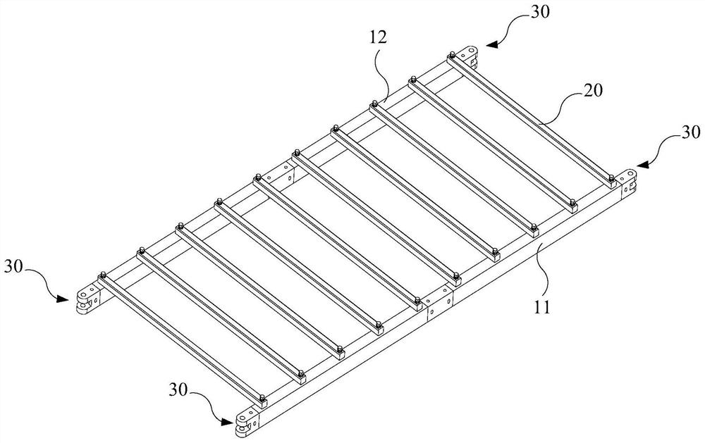
[0037] figure 1 It is a schematic diagram of a cable tray assembly provided by an embodiment of the present disclosure. Such as figure 1 As shown, the cable tray includes a first splicing rod 11 , a second splicing rod 12 , multiple supporting rods 20 and multiple connecting structures 30 .

[0038] The first splicing rods 11 and the second splicing rods 12 are coplanar and spaced apart. One end of the plurality of support rods 20 is connected to the first splicing rod 11 , and the other end of the plurality of support rods 20 is connected to the second splicing rod 12 .

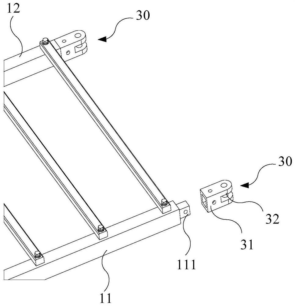
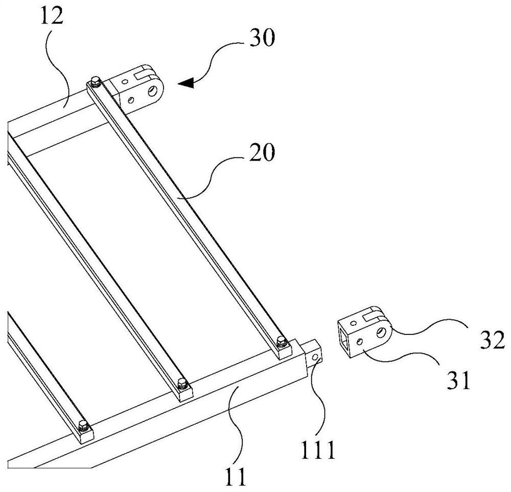
[0039] The first splicing rod 11 two ends on the end face and the second splicing rod 12 two ends on the end face all have the first straight prism protrusion ...


PUM


Abstract

The invention provides a cable bridge assembly and a cable bridge, and belongs to the field of bridges. The cable bridge assembly comprises a first splicing rod, a second splicing rod, a plurality ofsupporting rods and a plurality of connecting structures, the first splicing rod and the second splicing rod are arranged at an interval in a coplanar mode, one ends of the supporting rods are connected with the first splicing rod, and the other ends of the supporting rods are connected with the second splicing rod. The end faces of the two ends of the first splicing rod and the end faces of the two ends of the second splicing rod are each provided with a first straight prism protruding block, and each first straight prism protruding block is provided with a connecting structure. The connecting structure comprises a first connecting cylinder and a lug plate located at the closed end of the first connecting cylinder, the cross section of the inner wall of the first connecting cylinder is square, and the first connecting cylinder is detachably connected with the first straight prism protruding block. After the multiple cable bridge assemblies are hinged through the lug plates, the cablebridge assemblies can rotate in the horizontal plane or the vertical plane, the cable bridge can turn around, the angle can be flexibly adjusted, and the installation is convenient.

Description

technical field [0001] The present disclosure relates to the field of cable trays, in particular to a cable tray assembly and a cable tray. Background technique [0002] The cable tray is a support structure for laying cables, optical cables, etc., and is usually installed in a pipe gallery or inside a building to provide support for cables. [0003] Since cables need to be turned when laying, cable trays are usually not straight and will also turn. In the related art, cable trays are usually welded structures, that is, various rods are welded to form a surface for cables to be arranged, and curved rods are welded where corners are required. After the welding is completed, the shape of the cable tray is fixed. [0004] When the cable tray is laid, there are usually turns in the horizontal plane and in the vertical plane. During the production, it is necessary to set up different shapes of rods for welding according to the angle and direction of the turn. The manufacturing ...

Claims


Application Information

Patent Timeline
IPC IPC(8): H02G3/04H02G3/06
CPCH02G3/0456H02G3/0406H02G3/06
Inventor 李发涛
Owner WUHAN MARINE MACHINERY PLANT
Why Eureka
Try Eureka