An environment sanitation vehicle sweeping disk structure with turnover function

A technology for sanitation vehicles and sweepers, which is applied in road cleaning, construction, cleaning methods, etc., can solve the problems that the cornerstones on both sides of the road shoulder cannot be cleaned effectively and cannot meet the needs of high-standard cleaning, and achieve better cleaning results. ,Easy to operate and easy to clean

Pending Publication Date: 2018-11-27
黄松师
View PDF0 Cites 4 Cited by
  • Summary
  • Abstract
  • Description
  • Claims
  • Application Information

AI Technical Summary

Problems solved by technology

[0002] Most of the cleaning structures of the existing sanitation vehicles are fixed and designed on both sides of the bottom of the vehicle chassis. This design can only clean the flat road surface or road shoulders, and encounter low-lying groove

Method used


Image

  • An environment sanitation vehicle sweeping disk structure with turnover function
  • An environment sanitation vehicle sweeping disk structure with turnover function
  • An environment sanitation vehicle sweeping disk structure with turnover function

Examples


Example Embodiment

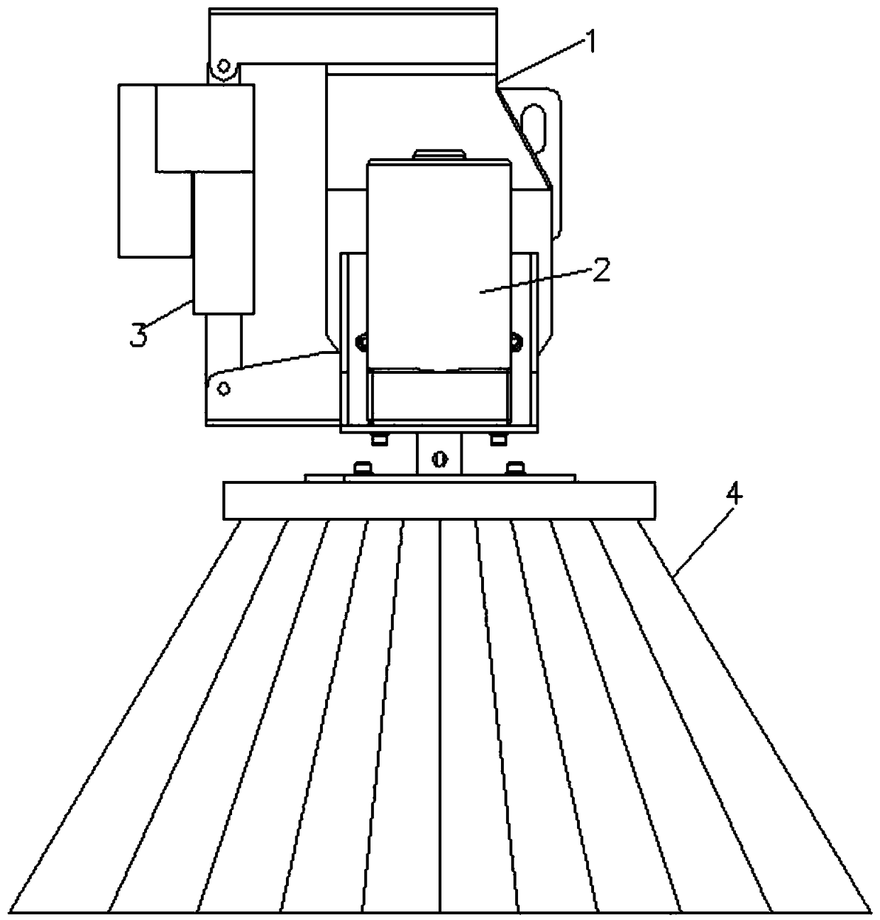
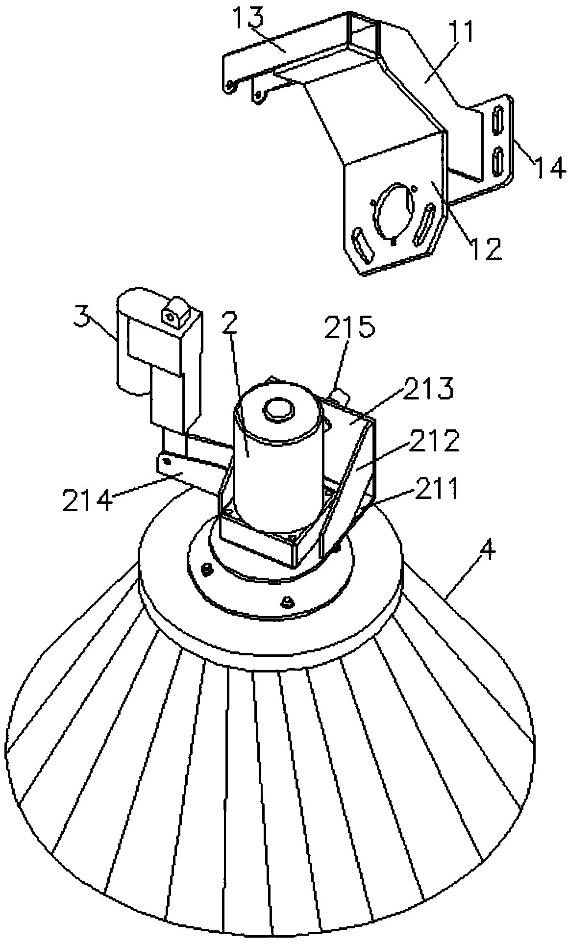
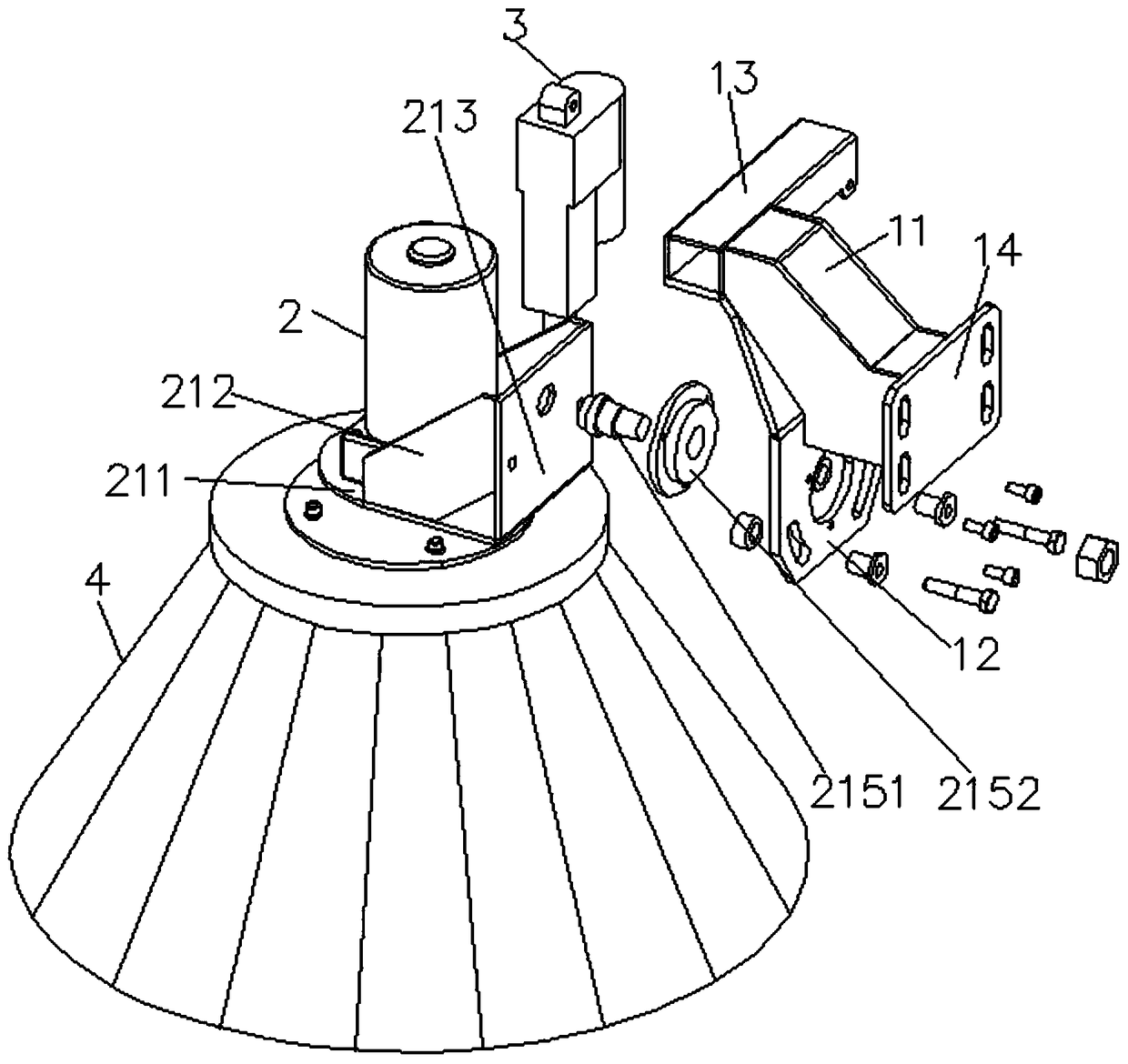
[0038] Embodiment one: if Figures 1 to 5 As shown, the sanitation vehicle sweeping structure with the flip function of this embodiment includes a fixed bracket assembly 1, a rotating drive mechanism 2, a telescopic device 3 and a sweeping assembly 4;

[0039] The above-mentioned rotary driving mechanism 2 is rotatably installed on the above-mentioned fixed bracket assembly 1 through the sweeping disc turning bracket 21;

[0040] The above-mentioned telescopic device 3 is arranged on one side of the above-mentioned sweeping disk turning bracket 21, and its fixed end is hinged with the above-mentioned fixing bracket assembly 1, and its telescopic end is downward, and is hinged with the above-mentioned sweeping disk turning bracket 21;

[0041] The above-mentioned sweeping disk assembly 4 is vertically arranged below the above-mentioned rotary drive mechanism 2, and its upper end is transmission-connected to the above-mentioned rotary drive mechanism 2;

[0042] The above-menti...

Example Embodiment

[0052] Embodiment two: if Figures 6 to 9 As shown, the road sweeping vehicle of this embodiment includes a car body (not shown in the figure) and the sweeping structure involved in Embodiment 1. The above-mentioned sweeping structure is provided with two, and is symmetrically distributed on the chassis of the above-mentioned car body On both sides below, the mounting plate 14 of the above-mentioned sweeping plate structure is respectively connected with the chassis lower end of the above-mentioned car body through the connecting arm, and the above-mentioned connecting arm (not shown in the figure) is rotatably connected with the chassis of the above-mentioned car body, and can drive the corresponding The above-mentioned sweeping plate structure rotates horizontally to the outside of the two sides of the above-mentioned chassis or the two sides below the chassis. The above-mentioned telescopic device 3 and the rotating drive mechanism 2 are respectively electrically connected t...


PUM


Abstract

The invention relates to a sweeper structure of an environmental sanitation vehicle and a road sweeper having a turning function. A sweep disk structure comprises a fixed bracket assembly, a rotary drive mechanism, a telescopic device and a sweep disk assembly; The rotary driving mechanism is rotatably mounted on the fixed bracket assembly through a sweeping disk turnover bracket. The rotary driving mechanism is rotatably mounted on the fixed bracket assembly through a sweeping disk turnover bracket. The telescopic device is arranged on one side of the sweeper turnover bracket, the fixed end of the telescopic device is hinged with the fixed bracket assembly, the telescopic end of the telescopic device is downward and hinged with the sweeper turnover bracket; A sweep disk assembly is vertically arranged below that rotary drive mechanism, and an upper end thereof is drivingly connected with the rotary drive mechanism; The rotary drive mechanism can drive the sweep disk assembly to rotate; The telescopic device drives the sweeper turnover bracket through the telescopic end, and the rotary drive mechanism and the sweeper assembly turn toward both ends thereof with respect to the stationary bracket assembly. The utility model has the advantages of simple structure, reasonable design, convenient operation and use, can flexibly adjust the angle of the sweeper assembly, and is favorable for sweeping the shoulders under multiple road conditions, and has good sweeping effect.

Description

technical field [0001] The invention relates to road surface cleaning technology, in particular to a sanitation vehicle sweeping structure with a turning function. Background technique [0002] Most of the cleaning structures of the existing sanitation vehicles are fixed and designed on both sides of the bottom of the vehicle chassis. This design can only clean the flat road surface or road shoulders, and encounter low-lying grooves or prominent slopes on the road shoulders, etc. Design, or when the cornerstones on both sides of the road shoulder cannot be effectively cleaned, it cannot meet the needs of high-standard cleaning of the road surface in modern urban construction and management. Contents of the invention [0003] The technical problem to be solved by the present invention is to provide a sanitation vehicle sweeping structure with a turning function, which effectively overcomes the defects of the prior art. [0004] The technical solution of the present inventi...

Claims


Application Information

Patent Timeline
IPC IPC(8): E01H1/05
CPCE01H1/053
Inventor 黄松师
Owner 黄松师
Why Eureka
Try Eureka