Air floatation high-speed electric main shaft

A high-speed motorized spindle and air flotation technology, used in clamping, supporting, positioning devices, etc., can solve the problems of piston thrust reduction and reduction, and achieve the effect of reducing heat generation, reducing friction loss, and reliable operation.

Active Publication Date: 2011-06-01
GUANGZHOU HAOZHI ELECTROMECHANICAL
View PDF3 Cites 38 Cited by
  • Summary
  • Abstract
  • Description
  • Claims
  • Application Information

AI Technical Summary

Problems solved by technology

There are pistons and partitions in the cylinder body of the main shaft, so it is necessary to drill a number of screw holes on the outer wall of the cylinder to fix the partitions, so the cylinder body generally requires a certain thickness, which results in unnecessary production costs. Secondly, the diameter of the piston is reduced due to the increase in the thickness of the cylinder, which reduces the thrust of the piston and causes unnecessary energy consumption

Method used


Image

  • Air floatation high-speed electric main shaft
  • Air floatation high-speed electric main shaft
  • Air floatation high-speed electric main shaft

Examples


Embodiment 1

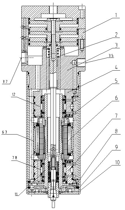
[0036] according to Figure 1 to Figure 12As shown in each figure of the present invention, the present invention is provided with gap isolation plate 8 at the radial periphery of the existing body assembly 10, cylinder return spring 2, upper air bearing 4, shaft core 5, shaft core 5 flange, gap isolation plate 8 On the basis of the thrust bearing 9 fixed on the upper surface, the present invention is particularly that the lower air bearing seat assembly 7 is fixed on the thrust bearing 9, the upper part of the lower air bearing seat assembly 7 is provided with a stator 6, and the front end of the shaft core 5 is provided with a chuck Attachment 11, the upper opening of the body assembly 10 is fixed with an aluminum water jacket assembly 3, the upper part of the aluminum water jacket assembly 3 is fixed with a tool change cylinder assembly 1;

Embodiment 2

[0038] Same as Embodiment 1, except that the lower air bearing seat assembly 7 includes a bearing seat 7.2, a radial outer water channel 7.7 on the middle side of the bearing boss of the bearing seat 7.2, and the outer water channel 7.7 near the bearing boss. Water and air seal rings 7.3 are provided on the upper and lower outer walls, and air seal rings 7.6 are provided around the bearing boss. Radial air passages 7.4 are provided near the head end of the bearing boss and near the bearing seat 7.2. The inner wall of the hole is provided with an inner bearing sleeve 7.1, and the head-to-tail connection between the inner bearing sleeve 7.1 and the inner wall of the through hole is provided with a vibration-damping sealing ring 7.5, and the middle part of the inner bearing sleeve 7.1 is provided with an inner water flow channel 7.8 and an outer water flow channel 7.7 In the same way, the inner bearing sleeve 7.1 is provided with an airflow outlet corresponding to the airflow pass...

Embodiment 3

[0040] Same as Embodiment 1, except that the stator 6 is provided with a water-cooling mechanism, which includes a power cord 6.5, a water tank 6.3 is provided on the outer wall of the stator 6, and a front sealing ring 6.2 and a rear sealing ring are respectively provided at both ends of the water tank 6.3 6.4 and the water tank 6.3 are evenly divided into a water outlet area 6.7 and a water inlet area 6.6, and a water inlet and return isolation block 6.8 is provided between the water outlet area 6.7 and the water inlet area 6.6.


PUM


Abstract

The invention relates to an air floatation high-speed electric main shaft, in particular to an air floatation high-speed electric main shaft for a machining tool. A lower air bearing block assembly 7 is fixed on a thrust bearing 9, the upper part of the lower air bearing block assembly 7 is provided with a stator 6, the front end of a shaft core 5 is provided with a chuck accessory 11, an aluminum water jacket assembly 3 is fixed at the upper opening of a body assembly 10, and a tool changing cylinder assembly 1 is fixed on the upper part of the aluminum water jacket assembly 3; and the middle part of the shaft body of an upper air bearing 4 is provided with an upper air bearing cooling water passage 12. The main shaft is an electromechanical integrated base piece with high revolution number and high precision, has simple and compact structure, and is convenient to install, high in heat dissipation efficiency, multifunctional and convenient for popularization and application.

Description

technical field [0001] The invention relates to a mechanical processing equipment, in particular to an air-floating high-speed electric spindle used for precise processing of PCBs. Background technique [0002] In the prior art, the aluminum water jacket assembly for the air-floating high-speed electric spindle has a complex structure, which is not conducive to heat dissipation of the spindle, inconvenient installation, single function, and difficult to grasp the assembly accuracy. The bearing seat assembly has a single structure, difficult processing, inconvenient loading and unloading, low heat dissipation capacity, and large vibration amplitude. The spindle chuck attachment is used to fix the tail of the chuck and increase the stability of the chuck. However, when the spindle rotates at high speed, the shaft bull will rub against the inner wall of the shaft core. There are pistons and partitions in the cylinder body of the main shaft, so it is necessary to drill a number...

Claims


Application Information

Patent Timeline
Patent Type & Authority Applications(China)
IPC IPC(8): B23B19/02B23Q11/00B23Q11/12B23Q3/12
Inventor 汤秀清
Owner GUANGZHOU HAOZHI ELECTROMECHANICAL
Why Eureka
Try Eureka