Cloth taking device for sewing machine capable of taking and feeding cloth fully automatically

A cloth device, fully automatic technology, applied in the direction of sewing machine components, cloth feeding mechanism, sewing equipment, etc., can solve the problems of low work efficiency, high labor intensity of operators, etc., achieve ingenious structural design, strong practicability, and reduce work intensity Effect

Inactive Publication Date: 2014-12-03
上海富山精密机械科技有限公司
5 Cites 34 Cited by

AI-Extracted Technical Summary

Problems solved by technology

[0004] The technical problem to be solved in the present invention is: during the working process of the automatic buttonhole machine, more or le...

Abstract

The invention relates to a cloth taking device for a sewing machine capable of taking and feeding cloth fully automatically. The cloth taking device comprises a horizontal guide rail, wherein the left-and-right sliding direction of the horizontal guide rail is X-direction, the vertical direction of the horizontal guide rail is Z-direction, and forward-backward direction of the horizontal guide rail is Y-direction; the cloth taking device can move in the X-direction along the horizontal guide rail under the driving of the power of a self driving system in whole and also can move in the Z-direction on the horizontal guide rail; a Y-direction linear module is arranged at the lower part of the cloth taking device; a rotating regulating mechanism is arranged at the lower part of the Y-direction linear module; a sucking disc fixing plate is arranged at the lower part of the rotating regulating mechanism; a sucking disc used for sucking the cloth and a pressure sensor are arranged on the sucking disc fixing plate; catching sucking power is provided by an air pump system. The invention provides an intelligent solution for feeding of the sewing machine, through the cloth taking device, the movement in the X-direction, the Y-direction and the Z-direction is realized, and the automatic cloth taking is realized.

Application Domain

Work-feeding means

Technology Topic

Pressure sensorSewing machine +4

Image

  • Cloth taking device for sewing machine capable of taking and feeding cloth fully automatically
  • Cloth taking device for sewing machine capable of taking and feeding cloth fully automatically
  • Cloth taking device for sewing machine capable of taking and feeding cloth fully automatically

Examples

  • Experimental program(1)

Example Embodiment

[0027] The present invention will be further described below with reference to specific embodiments and accompanying drawings.
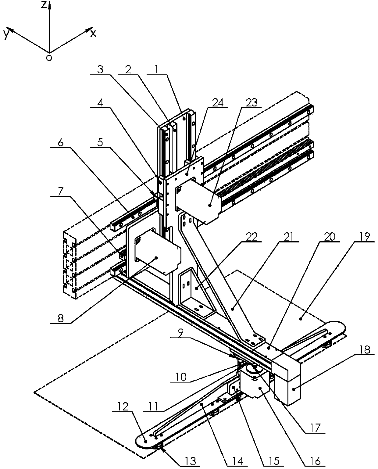
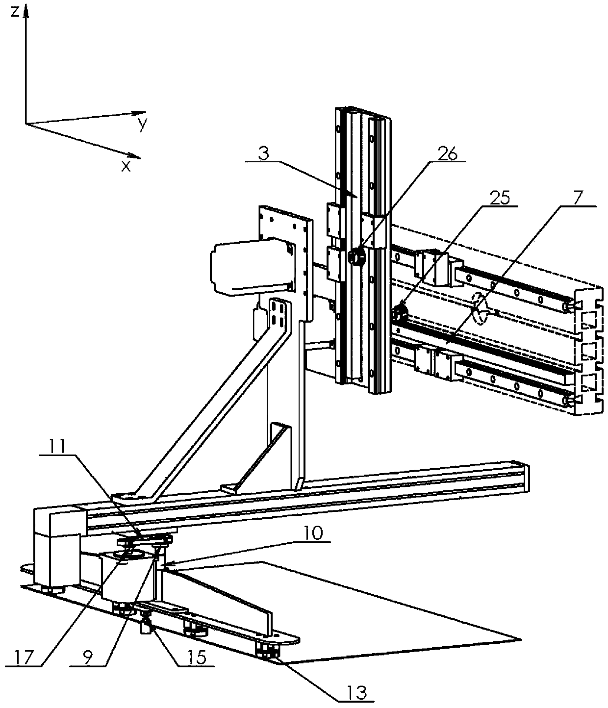
[0028] The subject of this embodiment is the cloth picking device of the automatic feeding placket buttonhole machine, which automatically picks up the cloth piece by piece through the pressure signal between the sensor detection sensor 15 and the cloth 19, and is driven by the picking cloth device itself. The system sends the cloth 19 to the specified required position.
[0029] see figure 1 , 2 , the left and right movement direction of the sewing press feed device is defined as the X-axis direction (left-right direction), the vertical movement direction of the picking device is defined as the Z-axis (up and down direction), and the X-axis direction and the Z-axis direction are perpendicular to both directions The direction of is defined as the Y-axis direction (front-back direction).
[0030] like Figure 4 The shown sensor adjustment screw 29 and sensor adjustment nut 28 are connected to the sensor 15 to form a pressure sensor assembly. The sensor adjustment screw 29 adjusts the length of its extension, and the sensor adjustment nut 28 locks the relative position of the sensor adjustment screw 29 on the sensor 15 . The pressure sensor assembly is mounted within the sensor housing 27 .
[0031] like image 3 As shown, rectangular holes are formed in the middle and one end of the suction cup fixing plate 1, and the pressure sensor assembly and the sensor housing 27 are respectively installed on the middle and one end of the sensor mounting member 2 through the two rectangular holes.
[0032] When the device for taking and distributing is moved to just above the fabric 19 by its own drive system, the motor in the vertical direction runs to drive the device for taking and distributing to move downward and press against the fabric 19 .
[0033] During the downward movement of the cloth taking device to press the cloth, the end faces of the sensor adjusting screws 29a and 29b in the sensor assembly installed on the sensor mounting member will first come into contact with the cloth 19 . As the cloth taking device continues to move downward, the contact pressure between the sensor adjustment screws 29a, 29b on the sensors 15a, 15b and the cloth 19 continues to increase.
[0034] The critical values ​​of the pressure signals of the sensors 15a and 15b are equal in magnitude. When the contact pressure between one of the sensor adjustment screws 29a and 29b on the sensors 15a and 15b and the cloth 19 reaches the critical value, then the sensor is at the threshold of the critical signal. Under the action, the Z-direction motor 23 stops running, and at the same time, the cloth suction cup 13 is controlled to ventilate and absorb the cloth, so as to realize the layer-by-layer suction of the cloth 19 .
[0035] When the cloth 19 is sucked, the driving system of the picking and distributing device controls the Z-direction motor 23 to operate in the set position and direction, and drives the Z-direction motor mounting plate 24 to move in the positive direction of the Z-axis, so that the cloth 19 is raised to a safe height.
[0036] After the cloth 19 is raised to a safe height, the Z-direction motor 23 stops running, and the Z-direction motor mounting plate 24 stops moving.
[0037] When the Z-direction motor stops running, the Y-direction motor 18 runs, and the synchronous belt drive in the module linear guide 20 drives the Y-direction moving member to move in the positive direction of the Y-axis; at the same time, the X-direction motor 8 runs, and the X-direction gear 25 is connected to the Y-axis. The meshing transmission of the X-direction rack 7, and then through the guiding action of the X-direction slider 5 and the X-direction guide rail 6, drives the X-direction moving member to move in the positive direction of the X-axis.
[0038] After the Y-direction moving member and the X-direction moving member move to the preset positions, the Y-direction motor 18 and the X-direction motor 8 stop running.
[0039] After the Y-direction motor 18 and the X-direction motor 8 stop running, the Z-direction motor 23 runs, through the meshing transmission between the Z-direction gear 26 and the Z-direction rack 2, and then through the guiding action of the Z-direction slider 4 and the Z-direction guide rail 3, Drives the Z-moving member to move to the specified position in the negative direction of the Z-axis.
[0040] When the Z-direction moving member moves down to a certain position, the air blowing pipe 28 is ventilated under the control of the solenoid valve, and the air flows through the small air holes of the pipe arm in the air blowing pipe 28 to blow the cloth to straighten the cloth 19 . The cloth 19 is sent to the preset position in cooperation with the cloth suction cup 13 and the Z-direction motor 23 . Assuming that the cloth 19 moves downward from the Z-direction moving member to a certain position until the cloth 19 is sent to the panel is time T, and the ventilation time of the air blowing pipe 28 is t, then t≤T, this setting can ensure the stability of the cloth falling It is not disturbed by air blowing, and the cloth position is more flat and accurate.
[0041] So far, the process of layer-by-layer suction and feeding of the fabric is completed.

PUM

no PUM

Description & Claims & Application Information

We can also present the details of the Description, Claims and Application information to help users get a comprehensive understanding of the technical details of the patent, such as background art, summary of invention, brief description of drawings, description of embodiments, and other original content. On the other hand, users can also determine the specific scope of protection of the technology through the list of claims; as well as understand the changes in the life cycle of the technology with the presentation of the patent timeline. Login to view more.

Similar technology patents

Waste transfer truck capable of cleaning dustbins

PendingCN111776553AImprove time utilizationReduce work intensity
Owner:王蔚然

Clamping structure for circuit board welding

InactiveCN104985377AReduce work intensityImprove welding precision
Owner:SICHUAN LANXUNBAOER ELECTRONICS TECH

Classification and recommendation of technical efficacy words

  • Reduce work intensity
  • Improve work efficiency

Powerless voltage automatic control system for area power grid

InactiveCN101106274AReduce network loss and operating costsReduce work intensity
Owner:SHANGHAI JIAO TONG UNIV

Quick automatic artillery aiming device

InactiveCN101881580AReduce work intensityImprove emission efficiency
Owner:ZHEJIANG UNIV OF TECH

Concrete laminating curing machine

Owner:盐城欣昌新型建材有限公司

Cooperation service platform facing different source data

InactiveCN101174957AImprove management level and qualityImprove work efficiency
Owner:NANJING UNIV OF FINANCE & ECONOMICS

Screw drilling tool, vertical drilling tool testing method and well inclination simulation testing equipment

InactiveCN111594144AReduced height requirementsImprove work efficiency
Owner:DEZHOU UNITED GASOLINEEUM MACHINERY

Method for intelligent automatic identification of transmission circuit parts

Owner:INFORMATION COMM COMPANY STATE GRID SHANDONG ELECTRIC POWER +2

Keyboard spill-proofing mechanism

ActiveUS7030330B2minimize manufacturing costimprove work efficiency
Owner:LITE ON SINGAPORE PTE LTD
Why Eureka
Try Eureka