On-bed functional training machine for burn patients

A technology of exercise equipment and functions, applied in hospital beds, gymnastics equipment, muscle training equipment and other directions, can solve the problems of increasing the work intensity of medical staff, unable to satisfy users, and patients unable to actively exercise, so as to achieve ease of use and improve comfort. Effect

Inactive Publication Date: 2020-09-04
CHANGZHOU NO 2 PEOPLES HOSPITAL
View PDF0 Cites 4 Cited by
  • Summary
  • Abstract
  • Description
  • Claims
  • Application Information

AI Technical Summary

Problems solved by technology

[0003] In the burn department of the hospital, burn patients will be treated. During the postoperative recovery period, burn patients cannot get out of bed due to their illness and need to rest in bed for a period of time. Appropriate exercise to promote the effect of rehabilitation. At present, hospitals generally use artificial methods to exercise the upper limbs of patients, which will increase the work intensity of medical staff. Patients cannot take the initiative to exercise and cannot meet the needs of users.

Method used


Image

  • On-bed functional training machine for burn patients
  • On-bed functional training machine for burn patients
  • On-bed functional training machine for burn patients

Examples


Embodiment 1

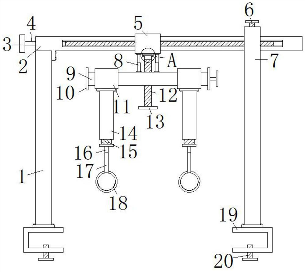
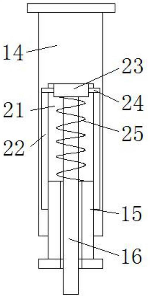
[0027] Embodiment one, with reference to figure 1 and figure 2 : A kind of bed functional exerciser for burn patients, comprising a first column 1, the top of the first column 1 is fixed with a hollow rod 2 by bolts, the outer wall of the hollow rod 2 is provided with a second column 7, and the outer wall of the hollow rod 2 A sliding sleeve 5 is set between the first column 1 and the second column 7, the bottom of the sliding sleeve 5 is fixed with two telescopic rods 8 by bolts, and the bottom of the two telescopic rods 8 is fixed with a load-bearing rod 9 by bolts, Two movable sleeves 11 are set on the outer wall of the load-bearing rod 9, and the bottoms of the two movable sleeves 11 are all fixed with positioning columns 14 by bolts, and the positioning columns 14 are provided with threaded inner chambers 21, and on the inner walls of the threaded inner chambers 21 Two slide grooves 22 are provided, and the bottom of the threaded inner cavity 21 is threadedly connected ...

Embodiment 2

[0028] Embodiment two, refer to figure 1 , Figure 4 , Figure 5 and Figure 6 : The front of the hollow rod 2 is provided with a long groove 32, and the hollow rod 2 is rotated to be provided with a one-way screw rod 4, and one end of the one-way screw rod 4 is extended to the outside of the hollow rod 2 to be welded with an adjustment wheel 3, and the inside of the sliding sleeve 5 A connection block 31 is welded, and the connection block 31 is located in the long groove 32, and the connection block 31 is threaded with the one-way screw mandrel 4, and the top center of the load-bearing rod 9 is threaded with a vertical screw mandrel 12, and the vertical screw mandrel 12 The smooth end cover is provided with a positioning sleeve 33, and the end of the vertical screw rod 12 located in the positioning sleeve 33 is welded with a rotating block 34, and the rotating block 34 is rotationally connected with the positioning sleeve 33, and the positioning sleeve 33 and the sliding s...

Embodiment 3

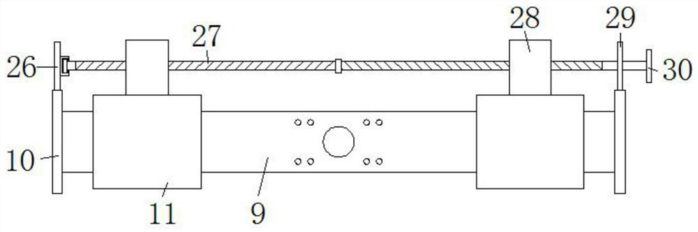
[0029] Embodiment three, refer to figure 1 and image 3Two limit blocks 10 are welded at the two ends of the load-bearing rod 9, and the backs of the two limit blocks 10 are respectively welded with a first positioning plate 26 and a second positioning plate 29, and the rotation in the second positioning plate 29 is provided with a two-way wire Rod 27, the smooth end of two-way screw mandrel 27 is rotationally connected with first positioning plate 26, and the other smooth end of two-way screw mandrel 27 is welded with handwheel 30, and the outer wall of two-way screw mandrel 27 is threadedly connected with two fixed blocks 28, Two fixed blocks 28 are respectively welded with two movable sleeves 11, and the top of the second column 7 is screwed with a positioning bolt 6, and the bottoms of the first column 1 and the second column 7 are fixed with a C-shaped block 19 by bolts, and C The bottom of shape block 19 is threadedly connected with fixed bolt 20, when installing this d...


PUM


Abstract

The invention discloses an on-bed functional training machine for burn patients. The on-bed functional training machine comprises a first stand column, wherein a hollow rod is fixed to the top of thefirst stand column through a bolt; a second stand column is arranged on the outer wall of the hollow rod in a sleeving mode; a sliding sleeve sleeves the part, located between the first stand column and the second stand column, of the outer wall of the hollow rod; and two telescopic rods are fixed to the bottom of the sliding sleeve through bolts. In the invention, a patient can hold pull rings byhand and downwardly pull the pull rings so as to realize active exercise of the upper limbs, and the work intensity of medical personnel is also reduced; thread adjusting blocks can be screwed to adjust the compression strength of return springs, so tension strength can be adjusted when the upper limbs of the patient are exercised; a one-way lead screw can be rotated to adjust the position of thesliding sleeve, so the two pull rings can be located above the patient, the patient does not need to be moved, and use is convenient; and meanwhile, a two-way lead screw can be rotated to adjust thedistance between the two pull rings, so use comfort is improved.

Description

technical field [0001] The invention belongs to the technical field of medical devices, in particular to a bed functional exerciser for burn patients. Background technique [0002] Burn, generally refers to heat, including tissue damage caused by hot liquid (water, soup, oil, etc.), steam, high-temperature gas, flame, hot metal liquid or solid (such as molten steel, steel ingot), etc., mainly refers to the skin and / or mucous membrane In severe cases, subcutaneous and / or submucosal tissues, such as muscles, bones, joints and even internal organs, may be injured. Scalds are tissue damage caused by hot liquid, steam, etc., and are a type of thermal burns. [0003] In the burn department of the hospital, burn patients will be treated. During the postoperative recovery period, burn patients cannot get out of bed due to their illness and need to rest in bed for a period of time. Appropriate exercise can promote the effect of rehabilitation. At present, hospitals generally use ma...

Claims


Application Information

Patent Timeline
Patent Type & Authority Applications(China)
IPC IPC(8): A63B23/12A63B21/055A61G7/05
CPCA61G7/05A63B21/055A63B23/12
Inventor 史强
Owner CHANGZHOU NO 2 PEOPLES HOSPITAL
Why Eureka
Try Eureka