Electric spiral cone rod extrusion oil tank oil drain hole equipment

A technology of electric screw and oil discharge hole, which is applied in the direction of mechanical equipment, fluid pressure actuation device, fluid pressure actuation system components, etc., can solve the problem of incomplete oil discharge of the fuel tank, and achieve complete oil discharge, smooth oil discharge, Guarantee the effect of drilling effect

Active Publication Date: 2022-02-11
NANJING COLLEGE OF INFORMATION TECH
View PDF0 Cites 0 Cited by
  • Summary
  • Abstract
  • Description
  • Claims
  • Application Information

AI Technical Summary

Problems solved by technology

[0003] The purpose of the present invention is to provide an electric screw taper rod to squeeze the oil tank oil discharge hole equipment to solve the problem of incomplete oil discharge from the oil tank caused by the equipment in the prior art

Method used


Image

  • Electric spiral cone rod extrusion oil tank oil drain hole equipment
  • Electric spiral cone rod extrusion oil tank oil drain hole equipment
  • Electric spiral cone rod extrusion oil tank oil drain hole equipment

Examples


Embodiment Construction

[0034] In order to make the technical means, creative features, goals and effects achieved by the present invention easy to understand, the present invention will be further described below in conjunction with specific embodiments.

[0035] It should be noted that, in the description of the present invention, the terms "front", "rear", "left", "right", "upper", "lower", "inner", "outer" and the like indicate orientations or positions The relationship is based on the orientation or positional relationship shown in the drawings, and is only for the convenience of describing the present invention and does not require that the present invention must be constructed and operated in a specific orientation, and thus should not be construed as a limitation of the present invention. The terms "front", "rear", "left", "right", "upper" and "lower" used in the description of the present invention refer to the directions in the drawings, and the terms "inner" and "outer" refer to is the dir...


PUM


Abstract

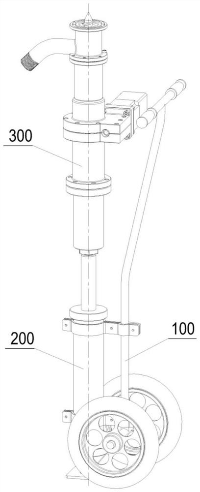
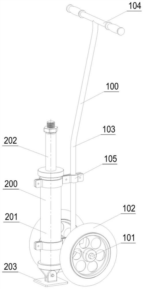
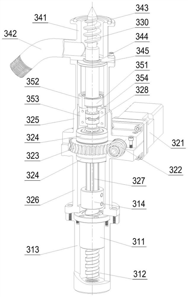
The invention discloses an electric screw taper rod extruding oil tank oil discharge hole equipment, which includes a lifting device and a working host connected to the output end of the lifting device; the working host includes a driving mechanism, a spiral cone and an oil cup; the driving mechanism includes a spline shaft, a spline The top surface of the key shaft is provided with a first end tooth; the bottom surface of the spiral cone is provided with a second end tooth, and the first end tooth and the second end tooth are connected through a coupling sleeve; the spiral cone has a first state and a second state. In the first state, the top of the spiral cone is located in the oil cup; in the second state, the top of the spiral cone is located above the oil cup; the device drives the spiral cone to rotate and rise through the driving mechanism, and the spiral cone can quickly Pierce the fuel tank, drive the mechanism and drive the spiral cone to descend, so that the oil in the fuel tank flows into the oil cup; when the spiral cone descends, the upward flange at the opening of the fuel tank will be pulled back downward through the outer spiral to make the fuel tank turn over The side is downward, which ensures the smooth and thorough oil discharge.

Description

technical field [0001] The invention relates to the technical field of oil tank cleaning equipment, in particular to equipment for squeezing the oil drain hole of the oil tank with an electric spiral cone rod. Background technique [0002] With the improvement of people's living standards, the number of cars owned is increasing, but the amount of scrapped cars is also increasing year by year. In China alone, nearly ten million cars need to be scrapped every year. Before the car is scrapped, it is first necessary to discharge the remaining gasoline and other oils in the fuel tank to reuse resources and avoid polluting the environment. In the past, the fuel tank was often disassembled and poured out manually, which not only requires a lot of work, but also has low efficiency and cannot meet the requirements of a large number of dismantling. Some enterprises have introduced foreign equipment and adopted the technology of piercing the fuel tank with a sharp cone to discharge oi...

Claims


Application Information

Patent Timeline
Patent Type & Authority Patents(China)
IPC IPC(8): B09B3/00B09B3/30F15B21/00B09B101/05
CPCB09B3/00F15B21/005
Inventor 熊江勇李重重庄丽丽王红然张世刚段付德李昕颖
Owner NANJING COLLEGE OF INFORMATION TECH
Why Eureka
Try Eureka