
Container-type mechanical shaft seal piece and double-end surface shaft seal piece comprising same

A mechanical shaft and cartridge technology, which is applied in the direction of engine seals, mechanical equipment, engine components, etc., can solve the problems of tediousness, deformation of seal parts, and lack of essential guarantee of sealing performance, etc.

Active Publication Date: 2014-04-09
AIDI MACHINE HANGZHOU
View PDF7 Cites 0 Cited by
  • Summary
  • Abstract
  • Description
  • Claims
  • Application Information

AI Technical Summary

Problems solved by technology

[0006] The technical problem solved by the present invention is that in the prior art, it is generally necessary to divide the sealing member into several parts for assembly, that is, to put each part of the sealing member on the pipe fitting to be installed in sequence and then fasten it with screws, which in turn leads to The installation process of the seal involves a series of cumbersome procedures, which greatly increases the labor consumption and reduces the work efficiency. The parts are easy to be worn and affect the sealing performance of the seal. The sealing parts occupy a large space, and the seal faces the current situation of poor oil discharge, which leads to the overheating of the seal and eventually causes the deformation and cracking of the parts. Cartridge mechanical shaft seal with optimized structure and double-end shaft seal composed of it

Method used


Image

  • Container-type mechanical shaft seal piece and double-end surface shaft seal piece comprising same
  • Container-type mechanical shaft seal piece and double-end surface shaft seal piece comprising same
  • Container-type mechanical shaft seal piece and double-end surface shaft seal piece comprising same

Examples


Embodiment Construction

[0026] The present invention will be described in further detail below in conjunction with the examples, but the protection scope of the present invention is not limited thereto.

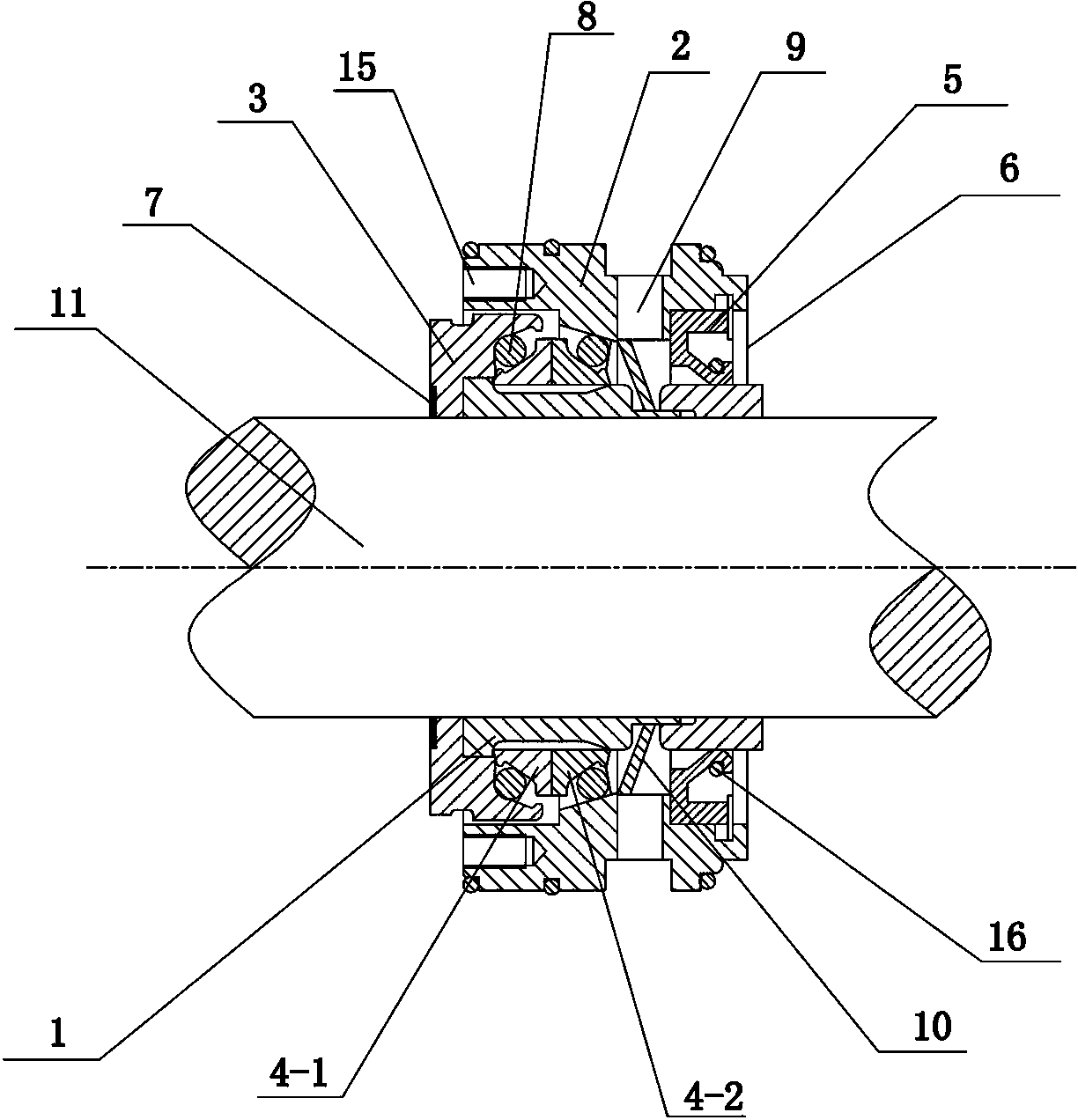
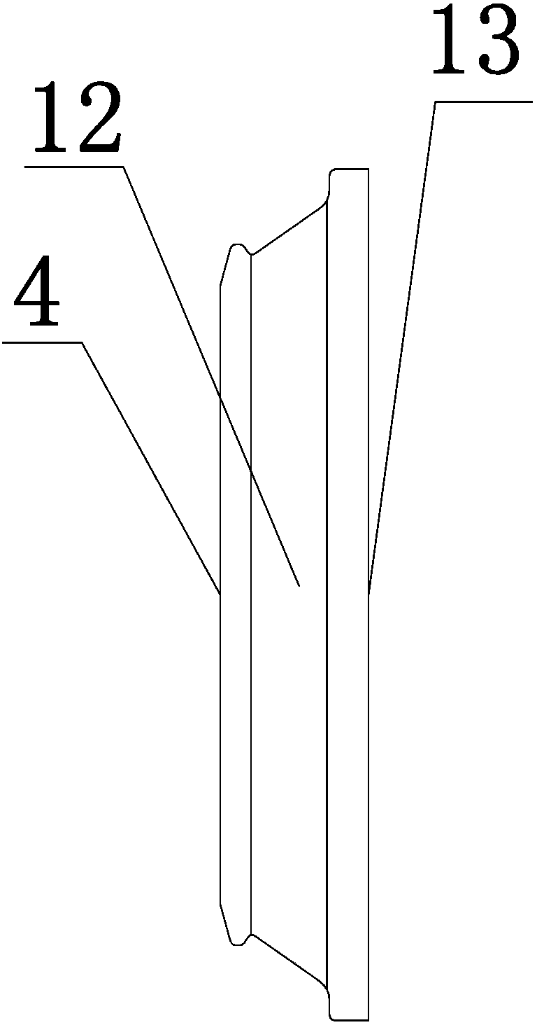
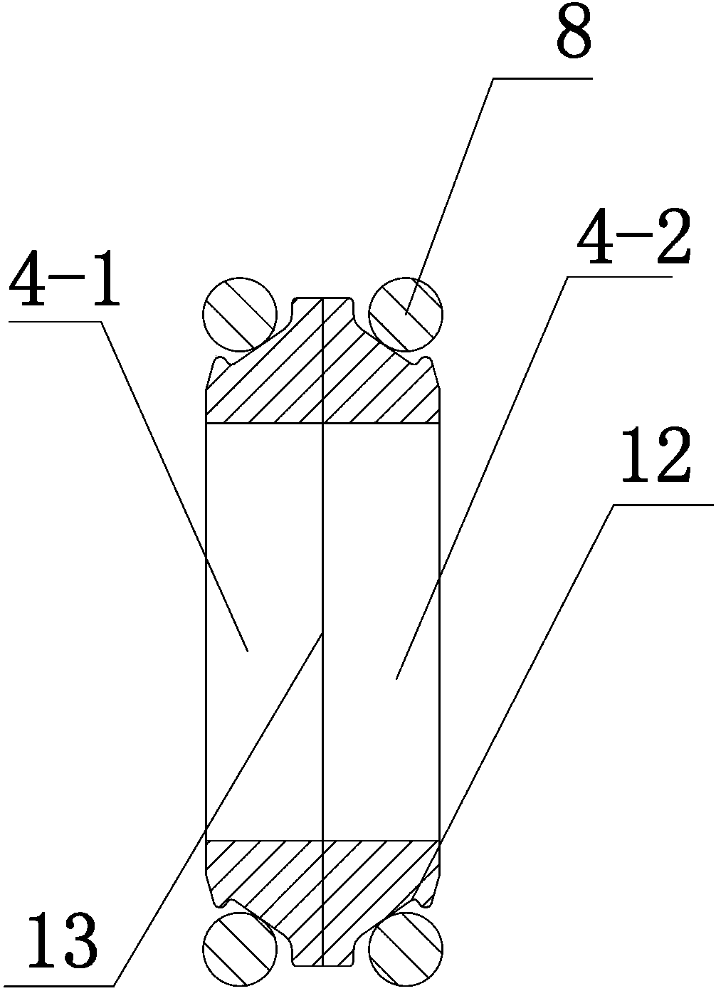
[0027] Such as figure 1 As shown, the present invention relates to a cartridge type mechanical shaft seal, comprising a fixed shaft sleeve 1, one side of the fixed shaft sleeve 1 is provided with a static seal column 2, and the other side is provided with a dynamic seal column 3, and the dynamic seal column 3 One side is provided with a sealing ring 4, the end of the static sealing column 2 is provided with an oil seal 5, the outer side of the oil seal 5 is provided with an expansion spring 6, and the outer side of the dynamic sealing column 3 is also provided with a baffle 7, the baffle 7, the dynamic sealing column 3. The sealing ring 4, the fixed shaft sleeve 1, the static sealing column 2, the oil seal 5 and the expansion spring 6 are concentrically arranged and connected in sequence. The dynam...


PUM


Abstract

The invention relates to a container-type mechanical shaft seal piece and a double-end surface shaft seal piece comprising the same; the container-type mechanical shaft seal piece comprises a block piece, a moving seal column, seal rings, a fixed shaft sleeve, a static seal column, an oil seal and an expanding spring which are arranged concentrically and connected sequentially; the moving seal column and the static seal column are respectively jointed on both sides of the fixed shaft sleeve; the outer surface of the moving seal column and the inner surface of the static seal column are jointed; the seal rings are arranged in a space formed by the moving seal column, the static seal column and the fixed shaft sleeve; first elastic rings are respectively arranged on the moving seal ring and the static seal ring; an oil outlet hole is arranged on the periphery of a joint between the static seal column and the fixed shaft sleeve, and an oil drain device is arranged at the joint between the fixed shaft sleeve and the static seal column; and the container-type mechanical shaft seal piece is connected through a connecting piece and forms the double-end surface shaft seal piece. The invention simplifies installation and detachment processes of the mechanical shaft seal piece, so that the mechanical shaft seal piece can be directly sleeved onto a pipe fitting, working hours are saved, the working efficiency is improved, the sealing performance is improved, the service life is prolonged, a seal part occupies a smaller space, the oil drainage is smooth, the radiating performance is good, and double seal can enhance the sealing performance.

Description

technical field [0001] The present invention belongs to engineering components or components; general measures for producing and maintaining effective operation of machines or equipment; general thermal insulation technical field, and particularly relates to a mechanical shaft seal which is integrated so that the sealing performance is greatly improved and its composition Double shaft seals. Background technique [0002] The transmission shaft is a circular object that can be moved or rotated by connecting or assembling various accessories. It is widely used in the mechanical field today. Since the transmission shaft runs through the inside and outside of the equipment, there is a circular gap between the transmission shaft and the equipment. The medium leaks outward through this gap, and if the pressure inside the equipment is lower than the atmospheric pressure, the air will leak into the equipment, so there must be a shaft seal device to prevent leakage. There are many t...

Claims


Application Information

Patent Timeline
Patent Type & Authority Patents(China)
IPC IPC(8): F16J15/16F16J15/18F16J15/34
Inventor 孙富强
Owner AIDI MACHINE HANGZHOU
Learn More