
Generating and receiving system applied to underwater vehicle wake flow induced Debye magnetic field
A technology of underwater vehicle and receiving system, which is applied in the use of magneto-optical equipment to measure the magnetic field, the size/direction of the magnetic field, etc., can solve the problems of weak Debye magnetic field strength, reduce the secondary interference magnetic field, and facilitate long-term The effect of simple use and structure
- Summary
- Abstract
- Description
- Claims
- Application Information
AI Technical Summary
Problems solved by technology
Method used
Image

Examples
Embodiment Construction
[0035] Below in conjunction with accompanying drawing and specific embodiment the present invention is described in further detail:
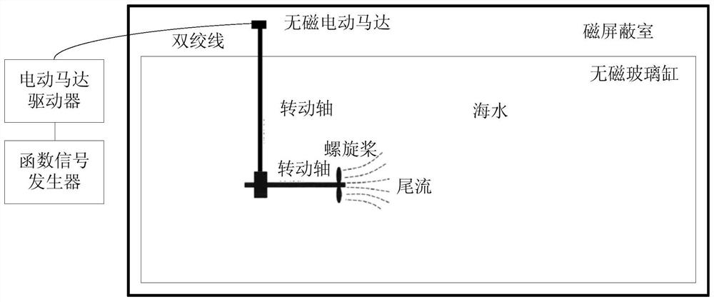
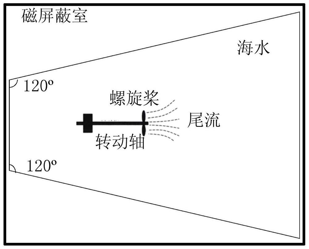
[0036] The present invention is applied to the generation and reception system of the Debye magnetic field induced by the wake of the underwater vehicle body, including a generation device and a receiving device, such as figure 1 Shown is the structural representation of the generating device of the present invention figure 1 (Sectional view); figure 2 Schematic diagram of the structure of the generating device of the present invention figure 2 ( figure 1 top view); where the generating device includes a magnetic shielding room, a non-magnetic power mechanism, a driving mechanism, a rotating mechanism and a non-magnetic container.
[0037] In an optional embodiment of the present invention, the non-magnetic container is an open structure, and the cross-section along the depth direction is an equilateral trapezoid, preferably the two included ...
PUM
 Abstract
Description
Claims
Application Information