
A transmission device suitable for I-shaped wheel to smoothly retract and pay off line

A transmission device and I-shaped wheel technology, which is applied in the direction of electromechanical devices, electric components, electrical components, etc., can solve the problems of site pollution, safety hazards, and uneven tension of winding lines, and achieve high work efficiency, safe use, and simple operation Effect

Active Publication Date: 2022-03-25
中钢集团郑州金属制品研究院股份有限公司
View PDF7 Cites 0 Cited by
  • Summary
  • Abstract
  • Description
  • Claims
  • Application Information

AI Technical Summary

Problems solved by technology

However, in the current existing power transmission devices, mechanical connection structures are often used between the rotating disc of the I-shaped wheel and the power transmission shaft (that is, the power shaft or the resistance shaft), such as mechanical connection transmissions such as pins, shift levers, chains or gears. On the one hand, after working for a long time, it is prone to unstable running tension and uneven winding tension; on the other hand, the sharp teeth of the gear are easy to hurt people, causing potential safety hazards; It will cause site pollution, and the greasy floor of the production workshop will easily cause operators to slip and fall

Method used


Image

  • A transmission device suitable for I-shaped wheel to smoothly retract and pay off line
  • A transmission device suitable for I-shaped wheel to smoothly retract and pay off line
  • A transmission device suitable for I-shaped wheel to smoothly retract and pay off line

Examples


Embodiment 1

[0023] Embodiment 1 (Embodiment 1 is a power device as an active take-up)

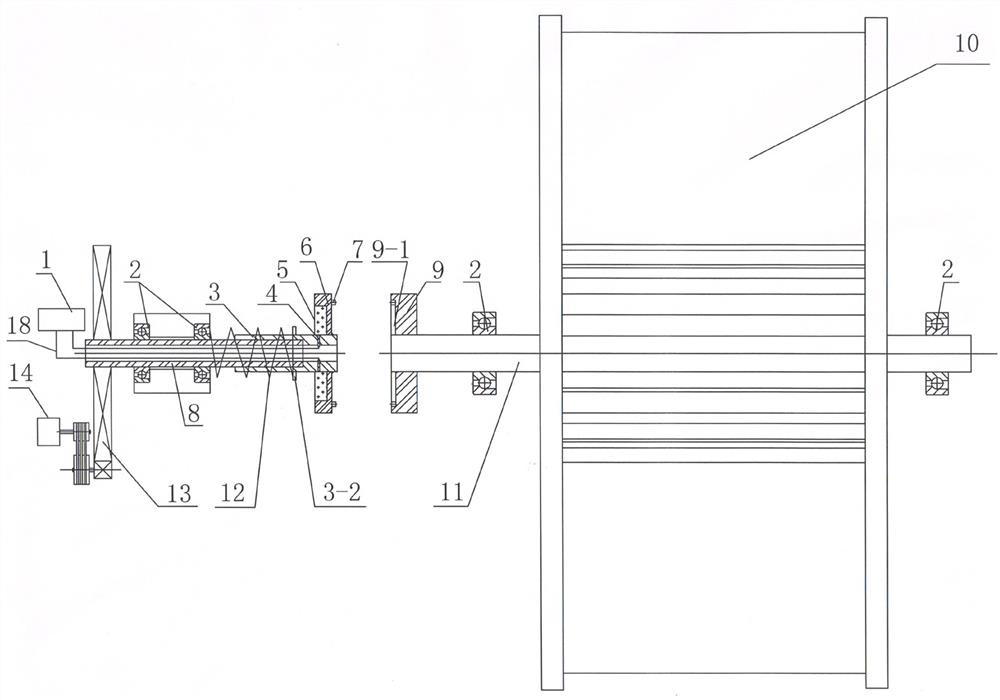
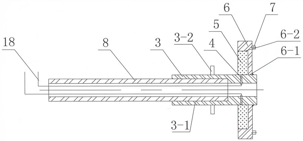
[0024] like Figure 1 to Figure 4 As shown, a transmission device of the present invention according to the first embodiment, which is suitable for the smooth retraction and payout of the I-shaped wheel, includes a force transmission shaft 8 driven by a force application device, a telescopic shaft 3 sleeved on the output end of the force transmission shaft, and fixed on the telescopic shaft 8. The magnetic power disk 6 at the output end of the shaft (the force application device generates power or resistance, and the power or resistance is transmitted to the magnetic power disk 6 through the force transmission shaft 8 and the telescopic shaft 3), and the soft magnetic core 5 embedded in the magnetic power disk, The I-wheel rotating disk 9 which rotates synchronously with the magnetic power disk through electromagnetic attraction and is installed on the input end of the I-wheel shaft 11, and the I-wheel...


PUM


Abstract

The invention discloses a transmission device suitable for a stable take-up and pay-off line of an I-shaped wheel, and belongs to the technical field of a steel wire take-up and pay-off line for deep processing of wire rods and wire rods. It includes a power transmission shaft driven by a force device, a telescopic shaft set at the output end of the power transmission shaft, a magnetic power disc fixed at the output end of the telescopic shaft, a soft magnetic core embedded in the magnetic power disc, and installed on the I-shaped wheel shaft. The rotating disk of the I-shaped wheel at the input end is set on the I-shaped wheel at the output end of the I-shaped wheel shaft; a conductive brush is embedded in the radial direction in the telescopic shaft, one end of the conductive brush is connected to the soft magnetic core, and the other end is connected to the magnetic force through the wire. device. In the present invention, the magnetic power disc and the rotating disc of the I-shaped wheel are automatically attracted by electromagnetic action to realize flexible connection and synchronous rotation, and can smoothly transmit power or resistance to the I-shaped wheel, so that the steel wire is always in a state of consistent tightness and uniform speed. It has the advantages of stable transmission, safe use, high work efficiency, clean and pollution-free, simple operation, time-saving and labor-saving.

Description

technical field [0001] The invention belongs to the technical field of wire reeling and reeling of wire rods for deep processing of metal products, and more particularly relates to a transmission device suitable for smooth rewinding and reeling of I-shaped wheels. Background technique [0002] In the process of drawing, the steel wire has to go through the processes of drawing, rolling and heat treatment. In the handover process of the above processes, an I-shaped wheel is required: that is, at the end of the previous process, the I-shaped wheel is used to automatically take up the wire, and it will be turned around. In the next process, the I-shaped wheel is used to passively pay off the wire. Active take-up or passive pay-off of the I-shaped wheel requires the transmission of power or resistance to the I-shaped wheel. Due to the self-weight of the I-shaped wheel and the weight of the steel wire, the I-shaped wheel needs to be rotated stably and with constant tension in th...

Claims


Application Information

Patent Timeline
Patent Type & Authority Patents(China)
IPC IPC(8): B21C47/04H02K7/10
CPCB21C47/04H02K7/10
Inventor 王宝玉刘小鹏蒋蕊汪凯张宇飞
Owner 中钢集团郑州金属制品研究院股份有限公司
Learn More