
Bonded insert mounting tensioner

A tensioning device and insert technology, applied in the direction of connecting components, material gluing, mechanical equipment, etc., can solve the problem that the insert nut and the fastening hole are not completely adhered and adhered, the connection strength is reduced, and the connection strength of the insert is affected, etc. problems, to achieve the effect of eliminating the influence of human factors, effective connection and fixation, and simple structure

Inactive Publication Date: 2016-02-24
CHINA AERO POLYTECH ESTAB
View PDF6 Cites 1 Cited by
  • Summary
  • Abstract
  • Description
  • Claims
  • Application Information

AI Technical Summary

Problems solved by technology

However, after the insert is glued, the bonding between the insert nut and the fastening hole requires a certain constant tension to press the two for a certain period of time before they can be completely cured, otherwise the insert nut and the composite material may not be completely adhered to each other. reduce the strength of the connection
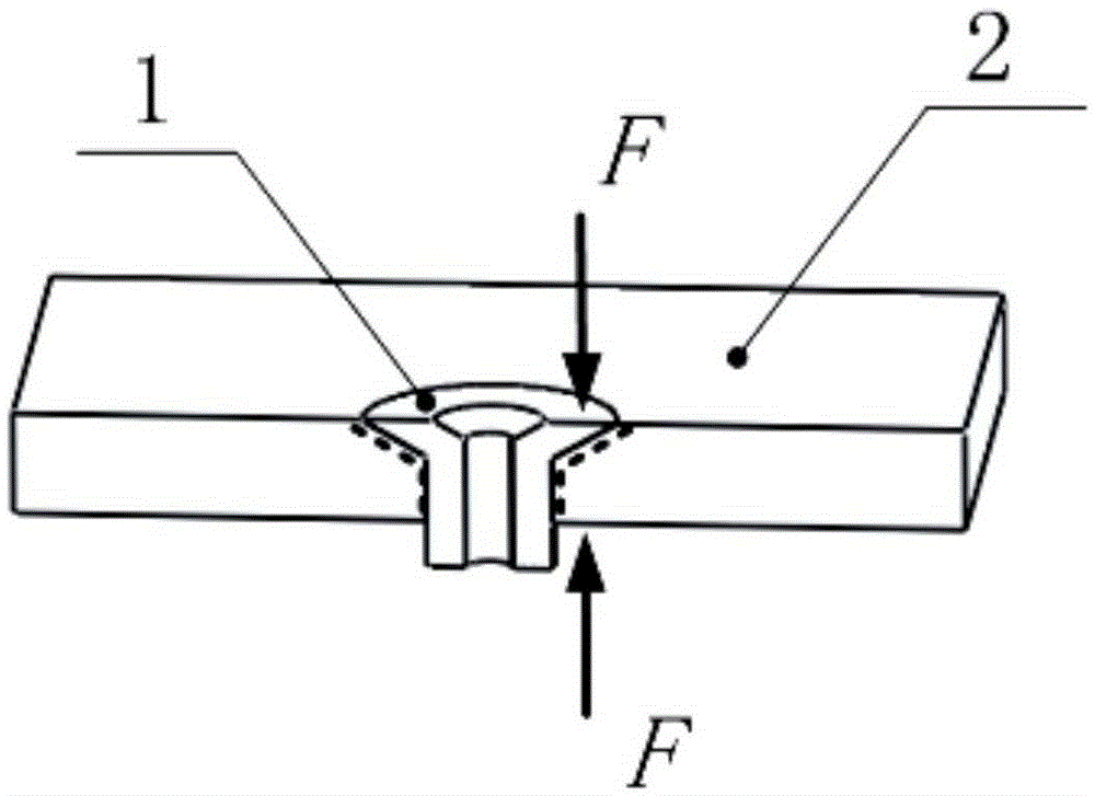
In the current installation process, manual or heavy objects are used to complete the bonding installation. Therefore, due to the influence of human factors and installation space factors, the nuts of the inlaid parts and the fastening holes are not fully bonded and bonded, which affects the connection strength of the inlaid parts.

Method used


Image

  • Bonded insert mounting tensioner
  • Bonded insert mounting tensioner
  • Bonded insert mounting tensioner

Examples


Embodiment Construction

[0019] Below by embodiment the present invention will be further described:

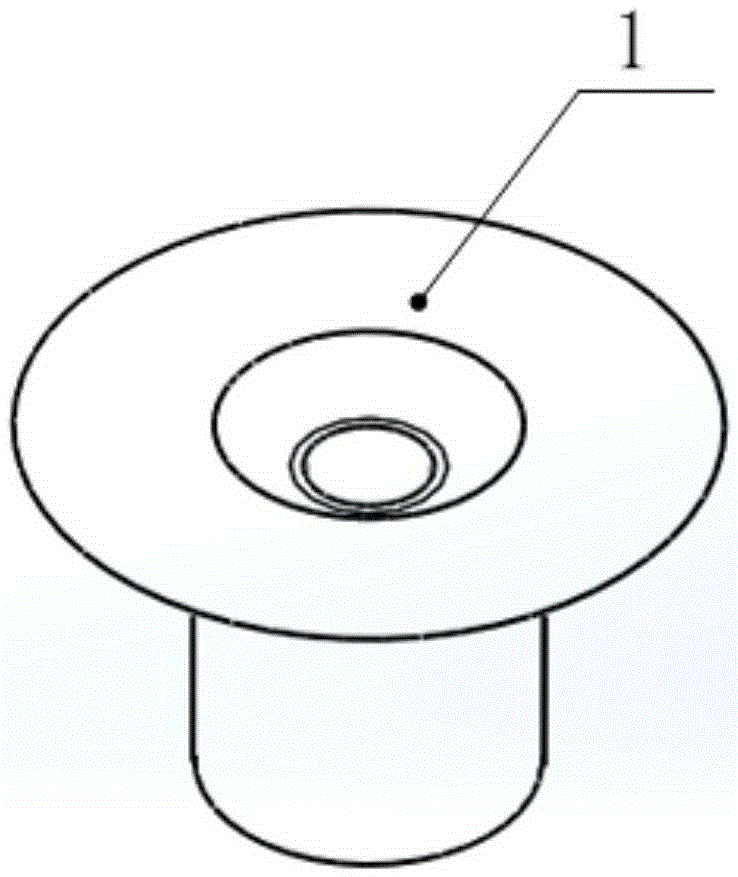
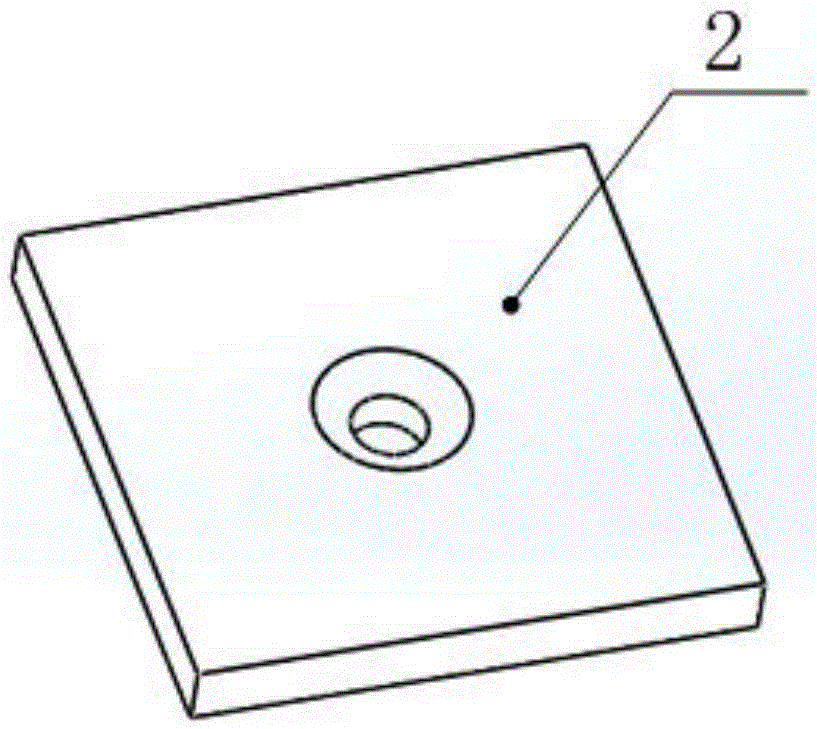
[0020] Please also see Figure 4 with Figure 5 ,in, Figure 4 It is a schematic diagram of the structure of the tensioning device for installing the bonding inlay of the present invention; Figure 5 yes Figure 4 The A-A cutaway diagram. The tensioning device for installing the adhesive insert includes an insert, a mounting plate, a tension rod, and a spring sheet. Among them, the inlay has a threaded hole in the middle, which is glued into the fastening hole of the mounting plate, the spring piece is folded into a groove structure, the two bottom surfaces are in contact with the bottom surface of the mounting plate, and a card with two symmetrical cards is set in the middle of the groove structure. One end of the tension rod is screwed to the inlay, and the other end passes through the slot of the spring sheet and is fixed by the card.

[0021] Such as Image 6 As shown, a support platform i...


PUM


Abstract

The invention belongs to an insert mounting technology and particularly relates to a bonded insert mounting tensioner. The bonded insert mounting tensioner comprises an insert, a mounting plate, a tensioning rod and a leaf spring, wherein the middle of the insert is provided with a threaded hole, the insert is bonded in a fastening hole of the mounting plate, the leaf spring is folded into a groove structure, the two bottom surfaces of the leaf spring are in contact with the bottom surface of the mounting plate, a clamping groove with two symmetrical clamping plates is formed in the middle of the groove structure, one end of the tensioning rod is connected with the insert in a screwed manner, the other end of the tensioning rod penetrates through the clamping groove of the leaf spring, and the tensioning rod is clamped and fixed by the clamping plates. The bonded insert mounting tensioner is simple in structure, convenient to mount, flexible in operation and stable and adjustable in tensioning force, can perform a stable tensioning function on the insert for a long time after the insert is mounted, impacts of human factors can be effectively eliminated, the effective connection and fixing of the bonded insert can be further realized, and the connecting strength of the insert is improved.

Description

technical field [0001] The invention belongs to the installation technology of inlaid parts, in particular to a tensioning device for bonding inlaid parts. Background technique [0002] Inserts are a kind of fasteners commonly used in aviation equipment, mainly composed of insert nuts and studs, such as figure 1 shown. When the inlay is connected to the metal structure, it is usually assembled by interference, such as figure 2 shown. However, with the application of a large number of high-performance composite materials in aviation equipment, the ability of composite materials to redistribute stress is poor. The traditional interference fit method may cause damage to the internal delamination of the composite material, so it is no longer suitable for the connection between the insert and the composite material. [0003] The adhesive connection between the insert and the composite material can effectively avoid the internal delamination damage of the composite material c...

Claims


Application Information

Patent Timeline
Patent Type & Authority Applications(China)
IPC IPC(8): F16B11/00
CPCF16B11/006
Inventor 陈雪梅刘静徐菁张辉刁小强樊西锋刘大鹏
Owner CHINA AERO POLYTECH ESTAB
Learn More