Unlock instant, AI-driven research and patent intelligence for your innovation.
3D structured light 940nm narrow-band optical filter and preparation method thereof
What is Al technical title?
Al technical title is built by PatSnap Al team. It summarizes the technical point description of the patent document.
A technology of narrow-band optical filter and structured light, which is applied in the field of optical filter to achieve the effect of accurate wavelength positioning and good steepness
Active Publication Date: 2020-09-08
苏州京浜光电科技股份有限公司
View PDF17 Cites 2 Cited by
Summary
Abstract
Description
Claims
Application Information
AI Technical Summary
This helps you quickly interpret patents by identifying the three key elements:
Problems solved by technology
Method used
Benefits of technology
Problems solved by technology
In this way, the conventional titanium dioxide / silicon dioxide combination cannot meet the requirements; for this reason, we propose a 3D structured light 940nm narrow-band filter and its preparation method
Method used
Image
Click on the blue label to locate the original text in one second.
Reading with bidirectional positioning of images and text.
Examples
Embodiment 1
[0020] see figure 1 , in an embodiment of the present invention, a 3D structured light 940nm narrow-band filter includes a substrate, one side of the substrate is alternately vapor-deposited with silicon oxide layers and hydrogenated silicon layers, and the other side of the substrate is alternately vapor-deposited with silicon oxide layers and For the hydrogenated silicon layer, the total number of layers of the silicon oxide layer and the hydrogenated silicon layer on each side is set to 20-40 layers.
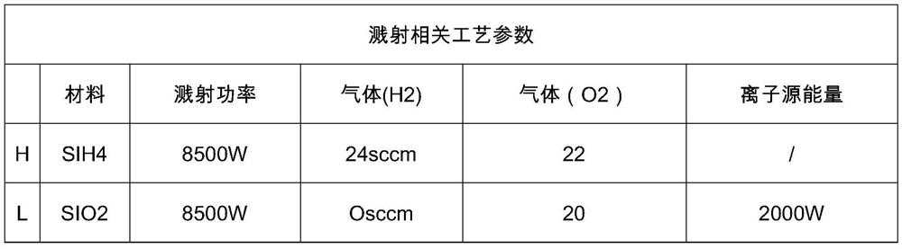
[0021] Preferably, the silicon oxide layer is set as a silicon dioxide layer, and the hydrogenated silicon layer is set as a silicon tetrahydrogen layer.
[0022] Preferably, the thickness of the silicon oxide layer on each side is set to 1300-2000 nm, and the thickness of the hydrogenated silicon layer on each side is set to 400-800 nm.
[0023] Preferably, the substrate is set to be AF32 glass or D263T glass.
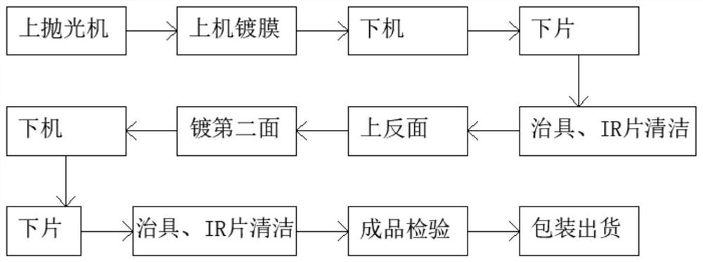
[0024] A preparation method of a 3D structured light 940nm na...
Embodiment 2
[0040] see figure 1 with figure 2 , in an embodiment of the present invention, a 3D structured light 940nm narrow-band filter includes a substrate, one side of the substrate is alternately vapor-deposited with silicon oxide layers and hydrogenated silicon layers, and the other side of the substrate is alternately vapor-deposited with silicon oxide layers and For the hydrogenated silicon layer, the total number of layers of the silicon oxide layer and the hydrogenated silicon layer on each side is set to 27 layers.
[0041] Preferably, the silicon oxide layer is set as a silicon dioxide layer, and the hydrogenated silicon layer is set as a silicon tetrahydrogen layer.
[0042] Preferably, the thickness of the outermost silicon oxide layer on each side is set to 100 nm, and 100 nm is the outermost layer in order to prevent the hydrogenated silicon layer from reacting with components in the air.
[0043] Preferably, the substrate is set to be AF32 glass or D263T glass.
[004...
PUM
Property
Measurement
Unit
thickness
aaaaa
aaaaa
thickness
aaaaa
aaaaa
thickness
aaaaa
aaaaa
Abstract
The invention discloses a 3D structured light 940 nm narrow-band optical filter and a preparation method thereof; the optical filter includes a substrate, wherein a silicon oxide layer and a siliconhydride layer are alternately evaporated on one surface of the substrate; the other surface of the substrate is alternately evaporated with silicon oxide layers and silicon hydride layers, the total number of the silicon oxide layers and the silicon hydride layers on each surface is set to be 20-40, the thickness of the silicon oxide layer on each surface is set to be 1300-2000nm, and the thickness of the silicon hydride layer on each surface is set to be 400-800nm. According to the optical filter, the refractive index of silicon hydride can be controlled to 3.8-4.5, the refractive index of silicon dioxide can reach 1.4-1.6, and the requirement for large angle and small offset can be met; the adopted film system scheme is accurate in wavelength positioning and good in steepness; the spacelayer is made of a high-refractive-index silicon hydride material, and the coupling layer is made of a low-refractive-index silicon dioxide material, so that the offset caused by the angle effect is smaller than that caused by the low-refractive-index material.
Description
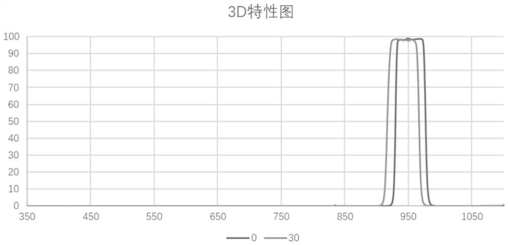
technical field [0001] The invention relates to the technical field of optical filters, in particular to a 3D structured light 940nm narrow-band optical filter and a preparation method thereof. Background technique [0002] At present, the narrow-band filter in the visible and near-infrared bands is a multilayer film composed of commonly used coating materials titanium dioxide and silicon dioxide alternately. The refractive indices of the two materials are 2.4 and 1.46 respectively, and their refractive index ratio is 1.64. When testing its spectral transmittance, it will be found that under the conditions of 0 degrees and 30 degrees, the wavelength shift is about 30nm (near the wavelength of 900nm). With the development of 3D camera technology, the corresponding filter is required The smaller the offset of the center wavelength (940nm) is, the better, and at the same time cut off the light in the rest of the bands to avoid interference caused by stray light. In this way, t...
Claims
Application Information
Patent Timeline
Application Date:The date an application was filed.
Publication Date:The date a patent or application was officially published.
First Publication Date:The earliest publication date of a patent with the same application number.
Issue Date:Publication date of the patent grant document.
PCT Entry Date:The Entry date of PCT National Phase.
Estimated Expiry Date:The statutory expiry date of a patent right according to the Patent Law, and it is the longest term of protection that the patent right can achieve without the termination of the patent right due to other reasons(Term extension factor has been taken into account ).
Invalid Date:Actual expiry date is based on effective date or publication date of legal transaction data of invalid patent.

