

Lens assembly, camera module and electronic equipment
A technology of camera module and lens assembly, which is applied in the direction of TV, electrical components, color TV, etc. It can solve the problems of unfavorable miniaturization design of camera module and increase of the volume of camera module, so as to meet the miniaturization design and increase the focus range Effect
- Summary
- Abstract
- Description
- Claims
- Application Information
AI Technical Summary
Problems solved by technology
Method used
Image

Examples
Embodiment approach 1
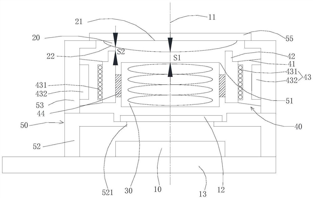
[0051] The camera module of the embodiment of the present application includes a lens assembly and a light sensor 10. The light sensor 10 is disposed on the light output side of the lens assembly and used to receive light passing through the lens assembly.
[0052] Such as figure 1 As shown, the lens assembly includes a lens base 50 , a first lens 30 , a liquid lens 20 and an extrusion structure 40 .
[0053] The first lens 30 is disposed on the mirror base 50 and can move along the optical axis 11 of the lens assembly.
[0054] The liquid lens 20 is disposed on the mirror base 50 .
[0055] The extruding structure 40 is disposed on the mirror base 50 for extruding the liquid lens 20 to adjust the direction of the light emitted by the liquid lens 20 .
[0056] The camera module can focus on the camera module by moving the first lens 30 and squeezing the liquid lens 20, and combining the two can increase the focus range of the camera module in a limited space, thereby meeting...
Embodiment approach 2
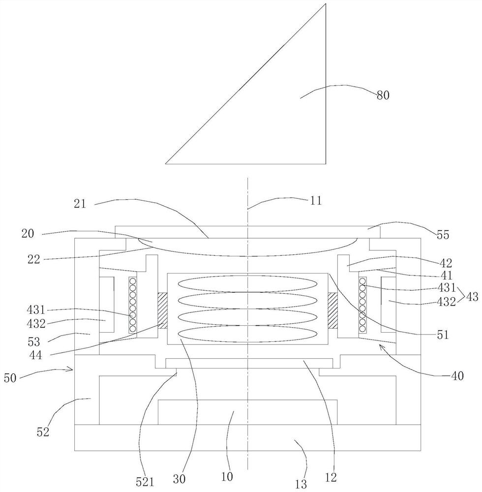
[0120] Compared with the first embodiment of the camera module, the main difference of this embodiment is that the camera module further includes a prism 80 .
[0121] The prism 80 is disposed on the light-incident side of the lens assembly, and the prism is used to divert the light incident on the prism and output to the light-incident side of the lens assembly.
[0122] The prism 80 is used to form a periscope camera module.
[0123] Specifically, the folded optical path of the prism 80 makes the height and even the overall size of the periscope camera module more compact, so it is suitable for electronic devices that require relatively high miniaturization, such as mobile phones, tablet computers, notebook computers, smart bracelets, smart Watches, smart helmets, smart glasses, etc.
[0124] Such as figure 2 As shown, in some embodiments, the prism 80 is disposed on the side of the liquid lens 20 facing away from the first lens 30 .
[0125] Other structures of the seco...
Embodiment approach 3
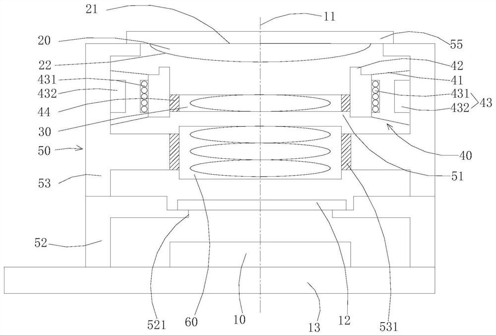
[0127] Compared with the first embodiment of the camera module, the main difference of this embodiment is that the lens assembly further includes a second lens 60 .
[0128] The second lens 60 is disposed on the mirror base 50 .
[0129] Such as image 3 As shown, the second lens 60 is located on the side of the first lens 30 away from the liquid lens 20 . The light emitted by the liquid lens 20 passes through the first lens 30 and the second lens 60 in sequence.
[0130]Specifically, there are one or more second lenses 60 , and the second lens 60 may be fixed relative to the light sensor 10 , or may be movable relative to the light sensor 10 .
[0131] For the type of the second lens 60, the second lens 60 can be a liquid lens or a solid lens. When a liquid lens is selected, at least one of its light-incident surface and light-emitting surface is an arc surface (the formation mode of the arc surface is not specified. limited). When a solid lens is selected, that is, the s...
PUM
 Abstract
Description
Claims
Application Information