
Optical lens, camera module and electronic equipment

An optical lens and camera module technology, applied in the field of optical imaging, can solve the problems of increased processing and molding difficulty, and achieve the effect of improving the capture ability and meeting the needs of high image quality design.

Inactive Publication Date: 2022-03-29
JIANGXI JINGCHAO OPTICAL CO LTD
View PDF0 Cites 1 Cited by
  • Summary
  • Abstract
  • Description
  • Claims
  • Application Information

AI Technical Summary

Problems solved by technology

However, with the introduction of thinner and lighter design requirements for smart phones, there are also requirements for the volume of the camera installed, and the size of the camera is also required to be miniaturized, which increases the difficulty of processing and molding the lenses of the camera. The imaging quality of the miniaturized camera poses a challenge

Method used


Image

  • Optical lens, camera module and electronic equipment
  • Optical lens, camera module and electronic equipment
  • Optical lens, camera module and electronic equipment

Examples


no. 1 example

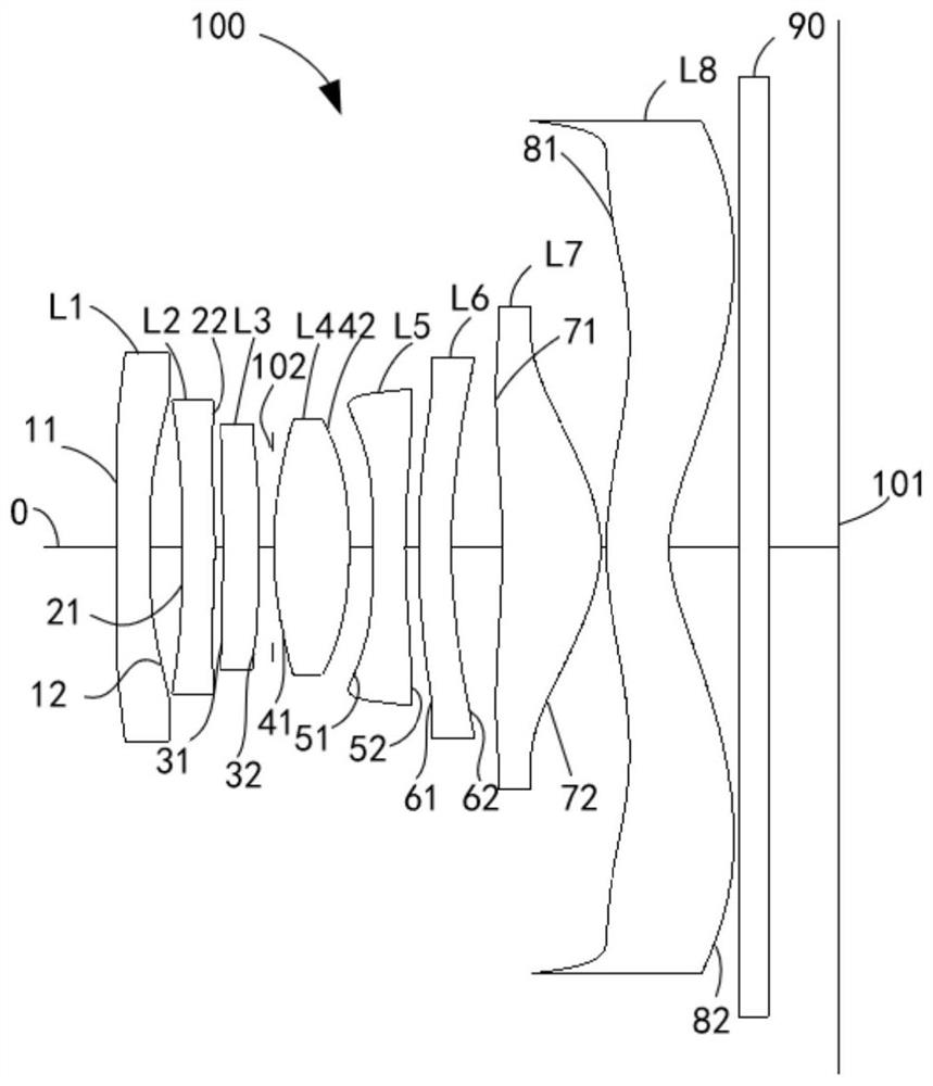
[0096] The structural diagram of the optical lens 100 disclosed in the first embodiment of the present application is as follows figure 1 As shown, the optical lens 100 includes a first lens L1, a second lens L2, a third lens L3, a diaphragm 102, a fourth lens L4, a fifth lens L5, a first lens L1, and a second lens L1 arranged in sequence from the object side to the image side along the optical axis O. Six lenses L6, seventh lens L7, eighth lens L8 and infrared filter 90.

[0097] Among them, the refractive power distribution of the above-mentioned eight-piece lens is shown in Table 1 below:

[0098] Table 1

[0099] Lens code L1 L2 L3 L4 L5 L6 L7 L8 Inflection force distribution burden just burden just burden burden just burden

[0100] Further, both the first object side 11 and the first image side 12 are concave at the near optical axis, the second object side 21 is concave at the near optical axis, and the second image side 22 i...

no. 2 example

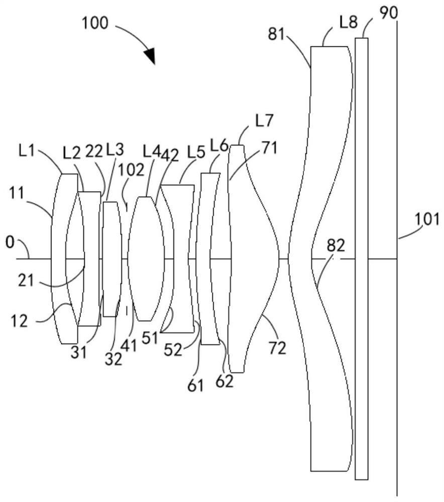
[0116] Please refer to image 3 , image 3 It is a schematic structural diagram of the optical lens 100 according to the second embodiment of the present application. The optical lens 100 includes a first lens L1, a second lens L2, a third lens L3, a diaphragm 102, a fourth lens L4, a fifth lens L5, and a sixth lens L6 arranged in sequence from the object side to the image side along the optical axis O , the seventh lens L7, the eighth lens L8 and the infrared filter 90.

[0117] Among them, the refractive power distribution of the above-mentioned eight-piece lens is shown in Table 4 below:

[0118] Table 4

[0119] Lens code L1 L2 L3 L4 L5 L6 L7 L8 Inflection force distribution burden burden just just burden burden just burden

[0120] Further, the first object side 11 and the first image side 12 are respectively convex and concave at the near optical axis, the second object side 21 is concave at the near optical axis, and the se...

no. 3 example

[0134] Please refer to Figure 5 , Figure 5 A schematic structural diagram of the optical lens 100 according to the third embodiment of the present application is shown. The optical lens 100 includes a first lens L1, a second lens L2, a third lens L3, a diaphragm 102, a fourth lens L4, a fifth lens L5, and a sixth lens L6 arranged in sequence from the object side to the image side along the optical axis O , the seventh lens L7, the eighth lens L8 and the infrared filter 90.

[0135] Among them, the refractive power distribution of the above-mentioned eight-piece lens is shown in Table 7 below:

[0136] Table 7

[0137] Lens code L1 L2 L3 L4 L5 L6 L7 L8 Inflection force distribution burden burden just just burden just just burden

[0138] Further, both the first object side 11 and the first image side 12 are concave at the near optical axis, the second object side 21 is concave at the near optical axis, and the second image side 2...


PUM


Abstract

An optical lens, a camera module and an electronic device, the optical lens comprises a first lens, a second lens, a third lens, a fourth lens, a fifth lens, a sixth lens, a seventh lens and an eighth lens which are sequentially arranged along an optical axis from an object side to an image side, the first lens has refractive power, the second lens has refractive power, the third lens has refractive power, the fourth lens has refractive power, the fifth lens has refractive power, the sixth lens has refractive power, and the eighth lens has refractive power. The fourth lens has positive refractive power, the object-side surface and the image-side surface of the fourth lens are convex surfaces near the optical axis, the fifth lens has negative refractive power, the sixth lens has refractive power, the seventh lens has refractive power, the eighth lens has refractive power, the object-side surface and the image-side surface of the eighth lens are convex surfaces and concave surfaces near the optical axis, and the optical lens meets the relational expression that Almax is less than or equal to 30deg. According to the optical lens, the camera module and the electronic equipment provided by the embodiment of the invention, the eight lenses are adopted, and the refractive power and the surface type of each lens are limited, so that the optical lens meets the design requirement of miniaturization, and the processing and forming difficulty of the lenses can be reduced.

Description

technical field [0001] The invention relates to the technical field of optical imaging, in particular to an optical lens, a camera module and electronic equipment. Background technique [0002] In recent years, with the advancement of the technology industry, imaging technology has continued to develop, and optical lenses for optical imaging have been widely used in electronic devices such as smartphones, tablet computers, and cameras. Taking smart phones as an example, in order to improve the shooting effect, it has become the mainstream in the smart phone market to carry one, two or even three or more cameras with different orientation functions in the mobile phone. However, with the introduction of thinner and lighter design requirements for smart phones, there are also requirements for the volume of the camera installed, and the size of the camera is required to be miniaturized, which increases the difficulty of processing and molding the lenses of the camera. The imagi...

Claims


Application Information

Patent Timeline
Patent Type & Authority Applications(China)
IPC IPC(8): H04N5/225H04M1/02
CPCH04M1/0264H04N23/54H04N23/57H04N23/55
Inventor 谭怡翔刘秀李明
Owner JIANGXI JINGCHAO OPTICAL CO LTD
Learn More