Thrombus extraction support device

A stent device and proximal technology, applied in the field of medical devices, can solve the problems of easy thrombus falling off, difficult operation, and large volume of the thrombus-replenishing net, and achieve fast recovery of blood flow, prevention of vasospasm, and high capture performance. Effect

Inactive Publication Date: 2016-04-13
威海维心医疗设备有限公司
View PDF11 Cites 30 Cited by
  • Summary
  • Abstract
  • Description
  • Claims
  • Application Information

AI Technical Summary

Problems solved by technology

[0004] The disadvantage of drug thrombolysis is that it is only suitable for small thrombus, and the treatment effect on large-volume thromboembolism is not ideal. Only about 3-5% of patients are suitable for drug thrombolysis.
[0005] Mechanical thrombectomy is to deliver the thrombus remover to the lesion site, and then take the thrombus out of the body through the sheath. Mechanical thrombectomy includes the following methods: Thrombectomy, this method removes the thrombus thoroughly, but causes too much damage to the vessel wall , can easily cause various complications; laser thrombectomy, this method is difficult to operate, if the laser energy is too low, it will be ineffective, and if the energy is too high, it will damage the blood vessels, and it will also cause various inflammations. The wall damage is small, but the blood clot is often unable to be caught; although the thrombus removal with the patching mesh is simple, it cannot be used in the intracranial blood vessels due to the large size of the patching mesh
[0006] Although Chinese patent 011148896 discloses an invention patent for a retrievable thrombus temporary filter that can be used in intracranial blood vessels, the disadvantages during thrombus removal are that the support force is insufficient, the thrombus is not firmly fixed, it is easy to fall off, there is no protection, and the structure is complicated
[0007] It can be seen that, using the current public technology to remove the thrombus, the plaque and broken thrombus on the blood vessel wall are easy to fall off and flow to the distal blood vessel, causing the risk of new embolism
[0008] In order to solve the above technical problems, CN104068912 discloses an intracranial vascular thrombus retriever and a thrombus retrieval device, which is composed of an outer stent and an inner stent, both of the inner and outer stents form a mesh, and the outer stent is coated Outside the inner stent, a gap is formed between the two. During the recovery process after the thrombus is captured, the thrombus is firmly fixed through the gap between the inner and outer stents. The substantial disadvantage is that this device does not consider the intracranial blood vessels. The intracranial blood vessels are very tortuous and the diameter is basically within 4mm. This method of superimposing the stent requires a large inner and outer diameter of the catheter, and when assembled into the catheter, a very hard catheter segment will be formed, making it impossible to reach the embolism site through the tortuous intracranial blood vessels
Even if it reaches the carotid artery, the blood clot can pass through the gap between the inner and outer stents during the capture process, but because the mesh of the inner stent is too small, the blood clot cannot enter the inner stent, resulting in an unstable state of the blood clot. , when the blood flows into the inner stent, it impacts the blood clot in the interlayer from the inside of the inner stent, causing the blood clot to flow out from the outer stent. Therefore, the substantive technical problem of new embolism caused by the shedding of the thrombus cannot be solved

Method used


Image

  • Thrombus extraction support device
  • Thrombus extraction support device
  • Thrombus extraction support device

Examples


Embodiment Construction

[0021] Below in conjunction with accompanying drawing, the present invention is further described:

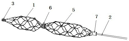
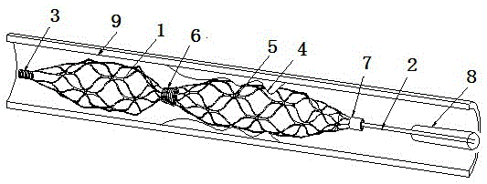
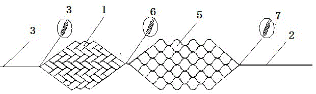
[0022] As shown in the drawings, a thrombectomy bracket device includes a thrombectomy bracket, a delivery guide wire 2, a guide wire 3 and a marking ring, the proximal thrombectomy bracket 5 and the distal protection bracket 1 are sealed at both ends. The mesh structure is characterized in that the thrombectomy bracket is composed of a proximal thrombectomy bracket 5 and a distal protection bracket 1, and the marker ring includes a middle segment marker ring 6, a proximal marker ring 7 and a distal marker. The proximal end of the distal protection bracket 1 is fixedly connected to the distal end of the proximal thrombectomy bracket 5 through the mid-section marking ring 6, and the distal end is fixedly connected to the distal marking and guide wire 3. The guide wire can guide and reduce the delivery of the bracket During the process, the compression of the microcatheter and th...


PUM


Abstract

The invention discloses a thrombus extraction support device. The thrombus extraction support device comprises a thrombus extraction support, a conveying guide wire, a guiding guide wire and marking rings, and is characterized in that the thrombus extraction support is composed of a front thrombus extraction support body and a back thrombus extraction support body; the marking rings include the middle-section marking ring and the near-end marking ring, the back end of the front thrombus extraction support body is fixedly connected with the back thrombus extraction support body through the middle-section marking ring, and the front end of the front thrombus extraction support body is fixedly connected with the guiding guide wire so that vascular irritation of the front thrombus extraction support body can be effectively reduced, and vasospasm in the thrombus extraction process can be prevented; the back end of the back thrombus extraction support body is fixedly connected with the near-end marking ring, the front end of the conveying guide wire is connected with the near-end marking ring, and the back end of the conveying guide wire is connected with a microtubule so that the front thrombus extraction support body and the back thrombus extraction support body can successively carry out thrombus extraction, and thrombus can be effectively prevented from falling in blood vessels. Due to the structure, the thrombus extraction support device has the advantages that the structure is simple, the capturing performance is high, thrombus extraction is complete, vasospasm is prevented, and the blood flow recovering velocity is high.

Description

technical field [0001] The invention relates to the technical field of medical instruments, in particular to a thrombectomy bracket device. Background technique [0002] Cerebral infarction (CI) is a general term for ischemic stroke, including cerebral thrombosis, lacunar infarction, and cerebral embolism, accounting for about 70% of all strokes. . Cerebral infarction is due to the sudden reduction or cessation of the blood flow of the local blood supply arteries of the brain tissue, resulting in ischemia and hypoxia of the brain tissue in the blood supply area of ​​the blood vessel, resulting in necrosis and softening of the brain tissue, accompanied by clinical symptoms and signs of the corresponding parts, such as hemiplegia , aphasia and other symptoms of neurological deficits. 24 to 48 hours after the onset of cerebral infarction, brain CT scans showed low-density lesions in the corresponding parts, with unclear boundaries, which may have a certain mass effect. Brain...

Claims


Application Information

Patent Timeline
Patent Type & Authority Applications(China)
IPC IPC(8): A61B17/221
CPCA61B17/221A61B2017/00778A61B2017/22038A61B2017/22045A61B2017/22047
Inventor 王东海田立剑俞华沣毕俊超刘文泽
Owner 威海维心医疗设备有限公司
Why Eureka
Try Eureka