Monitor equipment

A technology for monitors and equipment, applied in mechanical equipment, TVs, color TVs, etc., can solve problems such as inability to distinguish monitors, inability to select the controlled object well, and low reliability of infrared remote control

Inactive Publication Date: 2020-09-08
上海洋杰信息科技有限公司
View PDF0 Cites 0 Cited by
  • Summary
  • Abstract
  • Description
  • Claims
  • Application Information

AI Technical Summary

Problems solved by technology

In the prior art, when adjusting the parameters of the monitor, two methods are generally adopted. One way is to use the buttons on the monitor itself to adjust. When adjusting, you need to go to the front of the monitor to operate. Those who are too close to the screen wall can not feel the change of the adjustment effect well, and it is difficult to achieve a satisfactory adjustment effect, which brings great inconvenience to the use; another way is to use the infrared remote control to remotely adjust the monitor Operation, because multiple monitors form a screen wall, and the infrared remote control cannot distinguish the monitors. When using the infrared remote control for remote control adjustment, it usually controls multiple monitors at one time, which cannot be done well. Select the object to be controlled. If you want to control a single monitor through the remote control, you need to bring the remote control to the monitor and point it at the monitor for control. In fact, you have to walk in front of the monitor to realize single control. Use same inconvenience
In addition, the reliability of the infrared remote control itself is relatively low. If you want to use the infrared remote control to control and adjust all monitors, inconsistent control often occurs.

Method used


Image

  • Monitor equipment

Examples


Embodiment 1

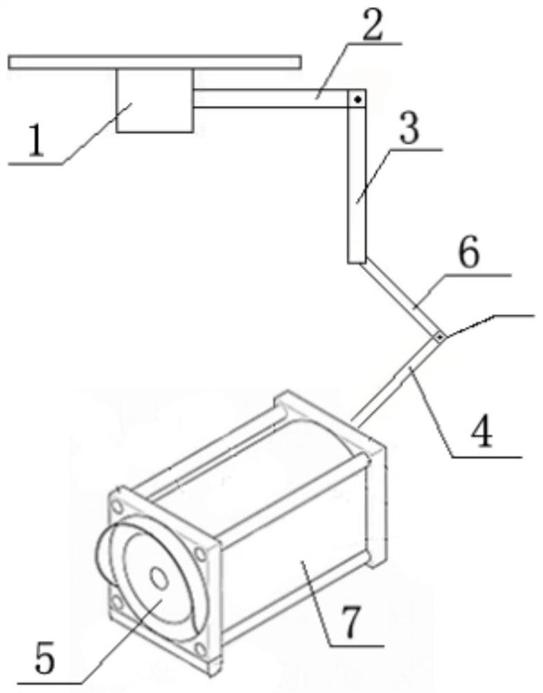
[0029] This embodiment provides a monitor device, including:

[0030] Including display, base and supporting body;

[0031] The supporting body includes a connecting rod and a rotatable vertical rod connected with the connecting rod;

[0032] The base is connected with the connecting rod; the non-connected end of the rotatable vertical rod is connected with the display with one end of the connecting rod;

[0033] The display can be rotated at one end of the connecting rod; the rotatable vertical rod can be rotated at one end of the connecting rod.

Embodiment approach

[0034] As an embodiment of the present invention, the display is provided with an image acquisition frame, a display main body and a display connecting rod; and the image acquisition frame is circular;

[0035] One end of the display connecting rod is fixed to the main body of the display; the other end of the display connecting rod is provided with a damping wheel; one side of the damping wheel is provided with a twist, and the other side of the damping wheel is connected through damping A rod is connected to the rotatable upright.

[0036] in. The horizontal cross-section of the base is a circle with a diameter of 10 cm.

[0037] The length of the connecting rod is 20cm.

[0038] The length of the rotatable vertical rod is 20cm.

[0039] The monitor device includes: an image acquisition module, a communication module, a control module and a power supply;

[0040] The image acquisition module includes an acquisition module, a controller, and a logic execution module;

[...

Embodiment 2

[0048] This embodiment provides a monitor device, including:

[0049] Including display, base and supporting body;

[0050] The supporting body includes a connecting rod and a rotatable vertical rod connected with the connecting rod;

[0051] The base is connected with the connecting rod; the non-connected end of the rotatable vertical rod is connected with the display with one end of the connecting rod;

[0052] The display can be rotated at one end of the connecting rod; the rotatable vertical rod can be rotated at one end of the connecting rod.

[0053] As an embodiment of the present invention, the display is provided with an image acquisition frame, a display main body and a display connecting rod; and the image acquisition frame is circular;

[0054] One end of the display connecting rod is fixed to the main body of the display; the other end of the display connecting rod is provided with a damping wheel; one side of the damping wheel is provided with a twist, and the ...


PUM


Abstract

The invention provides monitor equipment. The monitor equipment comprises a display, a base and a supporting main body, the supporting body comprises a connecting rod and a rotatable vertical rod connected with the connecting rod. The base is connected with the connecting rod; one end, which is not connected with the connecting rod, of the rotatable vertical rod is connected with the display; thedisplay can rotate at one end of the connecting rod; and the rotatable vertical rod can rotate at one end of the connecting rod. The display is provided with an image acquisition frame, a display mainbody and a display connecting rod; the image acquisition frame is circular; one end of the display connecting rod is fixedly connected with the display main body; a damping rotating wheel is arrangedat the other end of the display connecting rod; a knob is arranged on one side of the damping rotating wheel, and the other side of the damping rotating wheel is connected with the rotatable verticalrod through a damping connecting rod. The monitor equipment provided by the invention can be regulated and controlled in different time periods, and meanwhile, can perform 360-degree monitoring, so that loopholes are avoided.

Description

technical field [0001] The present invention relates to a monitor device, more particularly, a monitor device including an image recognition device. Background technique [0002] Recently, with the widespread use of computer systems, the demand for monitors is rapidly increasing. In this way, various monitors have been proposed, which have functions adapted to user's preference, thereby bringing convenience to the user. [0003] Monitoring is more and more widely used in people's daily life, and monitoring systems are installed in various places such as factories, communities, and office buildings. The monitoring system in the prior art usually mainly includes several parts such as a camera, a video switching matrix, a keyboard, and a monitor. The monitor for professional monitoring is different from an ordinary TV set. One screen wall to monitor different scenes at the same time. During the use of the monitoring system, it is usually necessary to adjust parameters such a...

Claims


Application Information

Patent Timeline
Patent Type & Authority Applications(China)
IPC IPC(8): H04N5/225H04N5/232F16M11/04F16M11/06F16M13/02
CPCF16M11/04F16M11/06F16M13/02H04N23/50H04N23/60
Inventor 万爱峰
Owner 上海洋杰信息科技有限公司
Why Eureka
Try Eureka