Bill binding device for finance

A technology for bills and finance, applied in the direction of using optical devices, binding, measuring devices, etc., can solve the problems of scrapped bills, broken binding pins, unable to sort bills, etc. The effect of time and effort

Active Publication Date: 2020-09-15
曹雪松
View PDF8 Cites 0 Cited by
  • Summary
  • Abstract
  • Description
  • Claims
  • Application Information

AI Technical Summary

Problems solved by technology

[0003] The main purpose of the present invention is to provide a bill binding device for financial use, which can effectively solve the problems in the background technology: the bills can only be simply bound, and the messy bills cannot be sorted, and the bills that have not been sorted may be due to binding The wrong position leads to the scrapping of the bill; the thickness of the bill cannot be automatically recognized, and the thick bill will cause the binding pin to break, resulting in binding failure

Method used


Image

  • Bill binding device for finance
  • Bill binding device for finance
  • Bill binding device for finance

Examples


Embodiment 1

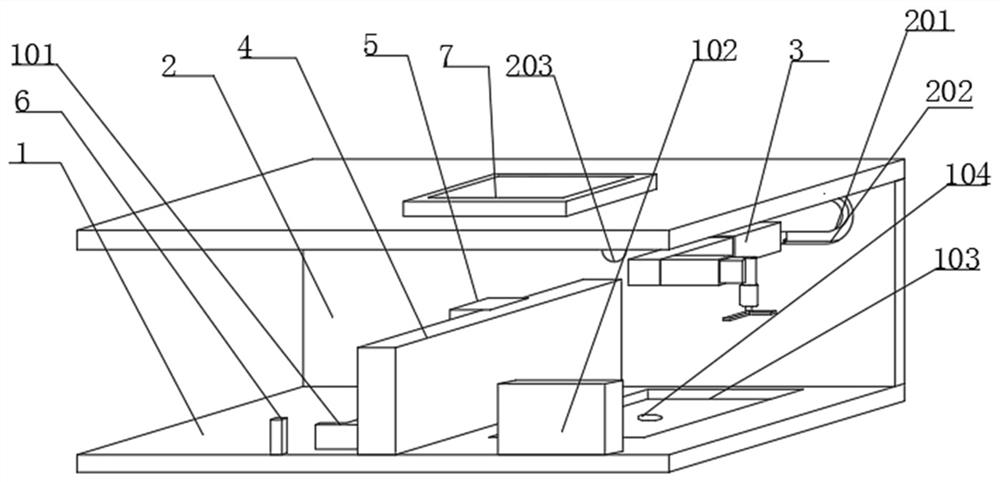
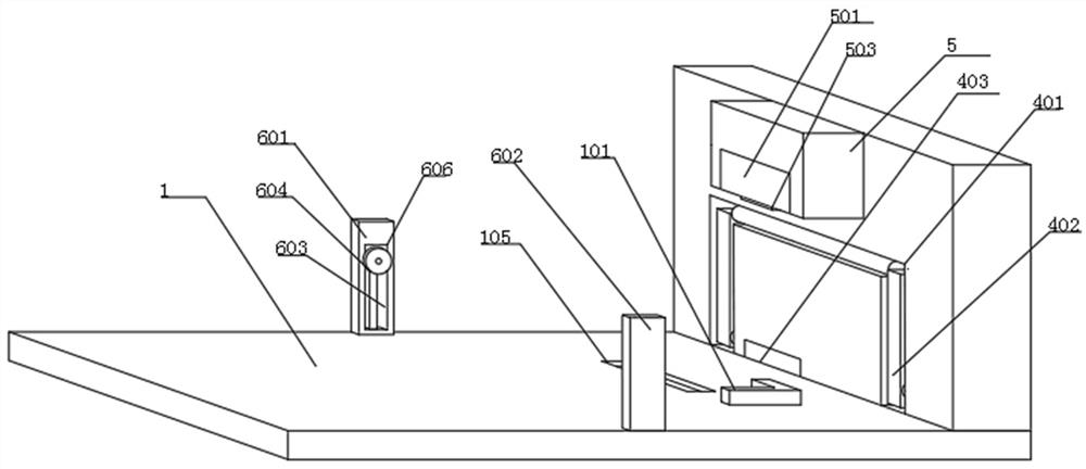
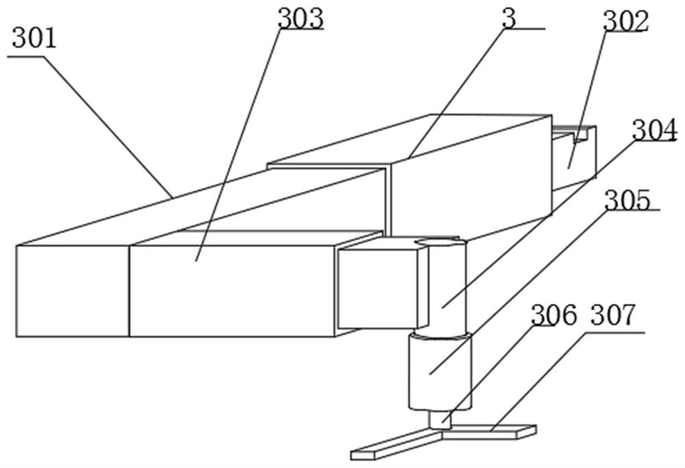
[0029] Such as Figure 1-7 As shown, a bill binding device for financial use includes a bottom plate (1) and a housing (2). The inner surface of the housing (2) is provided with a finishing mechanism (3), and the upper surface of the bottom plate (1) is located on the finishing A partition (4) is fixedly installed under the mechanism (3), a binding mechanism (5) is fixedly installed on the left side of the partition (4), and the upper surface of the bottom plate (1) is fixed on the left side of the partition (4). An identification mechanism (6) is installed, and a control display screen (7) is fixedly installed on the upper surface of the casing (2).

[0030] A limit plate (101) is fixedly installed on the upper surface of the bottom plate (1) and on the left side of the partition (4). The limit plate (101) is suitable for limiting the bills to be bound and preventing the bills from moving during the binding process. , the upper surface of the bottom plate (1) and the right s...

Embodiment 2

[0035] Such as Figure 1-7 As shown, a bill binding device for financial use includes a bottom plate (1) and a housing (2). The inner surface of the housing (2) is provided with a finishing mechanism (3), and the upper surface of the bottom plate (1) is located on the finishing A partition (4) is fixedly installed under the mechanism (3), a binding mechanism (5) is fixedly installed on the left side of the partition (4), and the upper surface of the bottom plate (1) is fixed on the left side of the partition (4). An identification mechanism (6) is installed, and a control display screen (7) is fixedly installed on the upper surface of the casing (2).

[0036] A limit plate (101) is fixedly installed on the upper surface of the bottom plate (1) and on the left side of the partition (4). The limit plate (101) is suitable for limiting the bills to be bound and preventing the bills from moving during the binding process. , the upper surface of the bottom plate (1) and the right s...


PUM


Abstract

The invention discloses a bill binding device for finance. The bill binding device for finance comprises a bottom plate and a shell, wherein an arrangement mechanism is arranged on the inner surface of the shell, a partition plate is fixedly installed on the upper surface of the bottom plate and located below the arrangement mechanism, a binding mechanism is fixedly installed on the left side of the partition plate, a recognition mechanism is fixedly installed on the upper surface of the bottom plate and located on the left side of the partition plate, and a control display screen is fixedly installed on the upper surface of the shell. According to the bill binding device for finance, disordered bills can be tidily arranged and then placed below the binding mechanism to be bound through the arrangement of the arrangement mechanism and the control display screen, so that the bills are tidily bound, meanwhile, bill scrapping caused by wrong binding positions of the bills is prevented, and the bill binding device for finance has certain creativity and practicability; and through cooperative use of the arranged binding mechanism and recognition mechanism, the thickness of the bills canbe monitored in real time, and thus binding needle breakage caused by the too large thickness of the bills is prevented.

Description

technical field [0001] The invention relates to the field of finance, in particular to the field of a bill binding device for finance. Background technique [0002] In the era of market economy, companies need to use a large number of bills. How to deal with the bills in finance, at this time, a bill binding device for finance is needed. There are some problems in the existing bill binding devices for finance. First, the existing The bill binding device for finance can only simply bind the bills, and cannot sort out the messy bills, and the bills that have not been sorted may be scrapped due to the wrong binding position. Secondly, the existing bill binding devices for finance cannot The thickness of the bill is automatically identified. If the bill is too thick, the binding pin will break and the binding will fail. To solve these problems, we propose a bill binding device for financial use. Contents of the invention [0003] The main purpose of the present invention is t...

Claims


Application Information

Patent Timeline
Patent Type & Authority Applications(China)
IPC IPC(8): B42B5/00G01B11/06G01B5/06
CPCB42B5/00G01B5/06G01B11/06
Inventor 刘雪侠
Owner 曹雪松
Why Eureka
Try Eureka