
Eureka
For R&D, Eureka makes reading and utilizing patents & technical documents easy.
Eureka AIR
Designed for self-driven R&D workflows. Generate viable solutions, solve complex R&D challenges, empower your innovation with AI.

Eureka Materials
Designed for material experts only. Revolutionize your material R&D, from search, analyze, to developing new materials.

TechResearch
Generate reliable direction feasibility study reports for your R&D in just a few steps.

TechSeek
Discover and master advanced knowledge NOW. Basics, ideas, possibilities, all at once.

TechMind
As an expert in R&D Theories, TechMind can generates customized viable solutions instantly.

TechRisk
Analyze your overall solution with one click, know your potential R&D risks in advance.

TechMonitor
Get weekly tech updates, stay abreast of the latest tech innovations and key insights.
Secondary equipment uninterruptible access bus voltage auxiliary device
A technology of bus voltage and secondary equipment, which is applied in the field of secondary equipment connected to bus voltage auxiliary devices without power failure, which can solve the problems of cumbersome operation and low efficiency, and achieve the effect of power conduction
- Summary
- Abstract
- Description
- Claims
- Application Information
AI Technical Summary
Problems solved by technology
Method used
Image

Examples
Embodiment 1
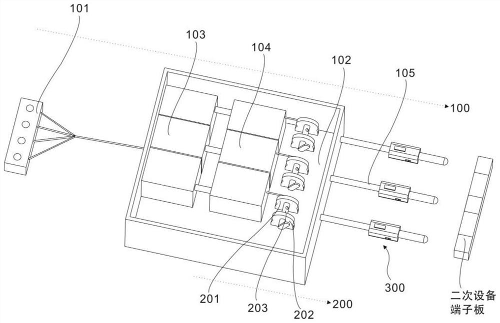
[0041] refer to Figure 1~2 , this embodiment provides an auxiliary device for connecting secondary equipment to the bus voltage without power failure, including a pressure measuring assembly 100, including a terminal board 101, a box body 102, an air switch 103, a voltmeter 104 and an external wire 105, and the air switch 103 and the voltmeter 104 are arranged in the box body 102, the terminal board 101 is electrically connected with the air switch 103, and the external wire 105 is electrically connected with the voltmeter 104;
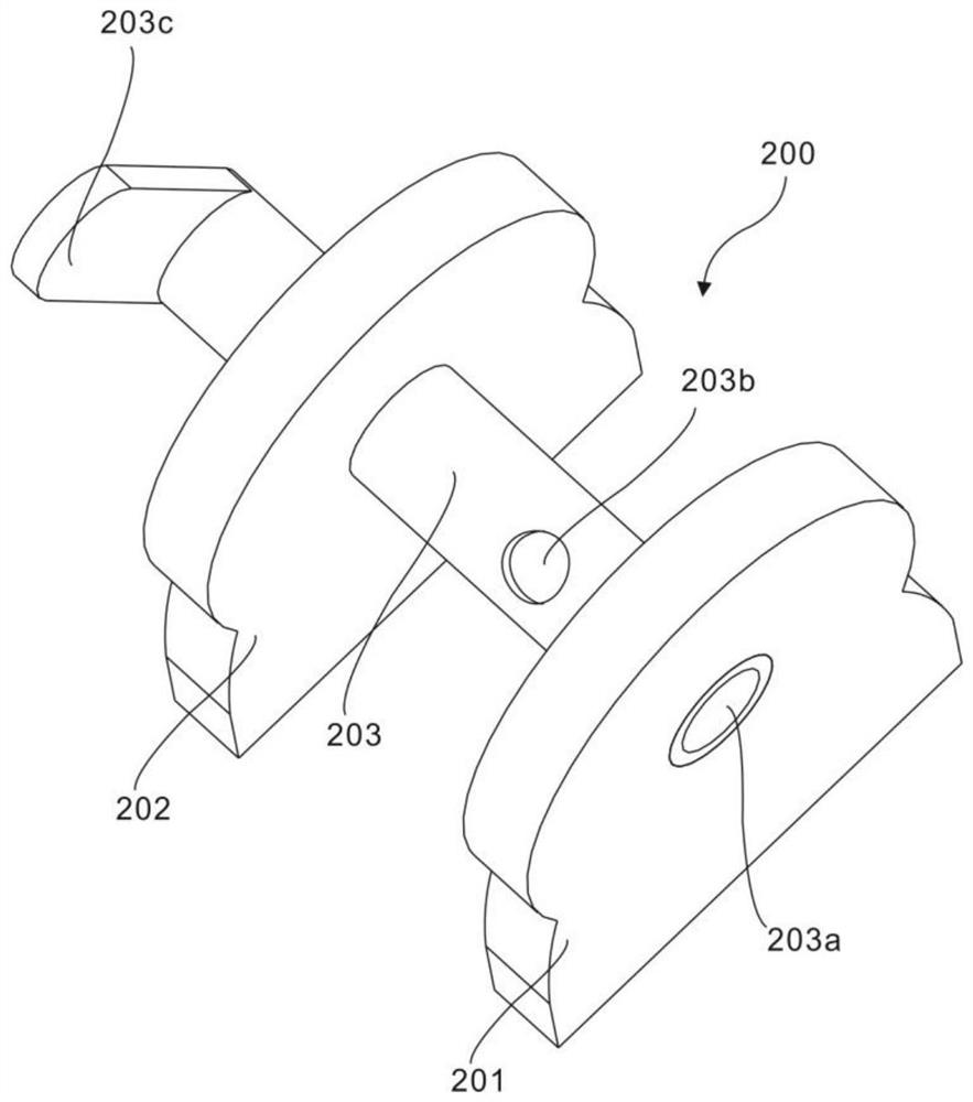
[0042] The winding assembly 200 includes a first support plate 201, a second support plate 202 and a roller 203, the first support plate 201 and the second support plate 202 are arranged relatively parallel, and the ends of the roller 203 are arranged between the first support plate 201 and the roller 203. on the second supporting board 202 .
[0043] The wire winding assembly 200 is arranged in the box body 102, and is arranged beside the voltmeter...
Embodiment 2
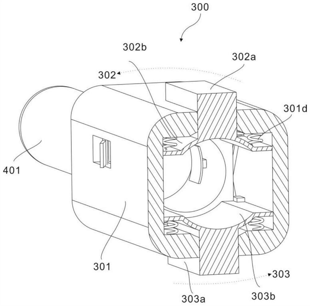
[0051] refer to Figure 1~6 The difference between this embodiment and the previous embodiment is that it includes a wiring assembly 300, including a box body 301, a first clamping piece 302 and a second clamping piece 303, and the first clamping plate 302 and the second clamping plate 303 are symmetrical set in the box body 301;
[0052] The conductive assembly 400 includes a plug post 401, a conductive bar 402, a push block 403 and a contact plate 404, the plug post 401 is arranged at the end of the box body 301, and the conductive bar 402, the push block 403 and the contact plate 404 are set at the box body 301 Inside;
[0053] The conductive strip 402 is connected to the plug column 401 and the push block 403, and the contact plate 404 is arranged at the end of the push block 403;
[0054] The connection assembly 500 includes a pusher 501 and a lock 502 , the pusher 501 connects the wiring assembly 300 and the conductive assembly 400 , and the lock 502 is arranged on the...
Embodiment 3
[0082] refer to Figure 1-7 The difference between this embodiment and the previous embodiment is that a side groove 301i is provided on the side of the box body 301, and the side groove 301i communicates with the accommodating groove 301e.
[0083] The locking member 502 includes a plywood 502a, a buckle 502b and a rotating shaft 502c. The buckle 502b is disposed at the end of the plywood 502a, and the plywood 502a is connected to the side groove 301i through the rotating shaft 502c.
[0084] The end of the vertical bar 501c facing the propulsion block 403 is set as a second slope 501c-1, and the side of the vertical bar 501c is provided with a slot 502c-2.
[0085] In this embodiment, in order to maintain the clamping state of the wiring assembly 300, a locking member 502 is provided. The locking member 502 can rotate around the rotating shaft 502c. It should also be noted that a torsion spring is arranged on the rotating shaft 502c, and the torsion spring is in a natural st...
PUM
 Abstract
Description
Claims
Application Information
 - R&D Engineer
- R&D Manager
- IP Professional
- Industry Leading Data Capabilities
- Powerful AI technology
- Patent DNA Extraction
Browse by: Latest US Patents, China's latest patents, Technical Efficacy Thesaurus, Application Domain, Technology Topic, Popular Technical Reports.
© 2024 PatSnap. All rights reserved.Legal|Privacy policy|Modern Slavery Act Transparency Statement|Sitemap|About US| Contact US: help@patsnap.com