Unmanned aerial vehicle landing method and device and electronic equipment
A UAV, landing point technology, applied in non-electric variable control, vehicle position/route/altitude control, instruments and other directions, can solve the problem of low positioning accuracy, decreased landing success rate of UAV, unable to reach UAV Unmanned management requirements and other issues to achieve the effect of alleviating large positioning errors and improving positioning accuracy
- Summary
- Abstract
- Description
- Claims
- Application Information
AI Technical Summary
Problems solved by technology
Method used
Image
Examples
no. 1 example
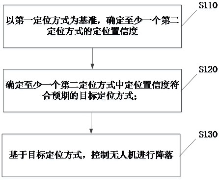
[0044] figure 1 A schematic flowchart of a method for landing a drone provided by an embodiment of the present invention is shown.
[0045] refer to figure 1 , the drone landing method includes the following steps:
[0046]Step S110, based on the first positioning method, determine the position reliability of at least one second positioning method;
[0047] Specifically, the positioning reliability of at least one second positioning manner may be determined based on the positioning reliability of the first positioning manner.
[0048] Among them, the above-mentioned location reliability can be location error (for example, ±10cm), location accuracy (for example, location accuracy is accurate to centimeter level, that is, centimeter-level location accuracy), and of course location location reliability can also be determined according to location error (or location accuracy) For example, it can be determined according to the functional relationship between the positioning reli...
no. 2 example
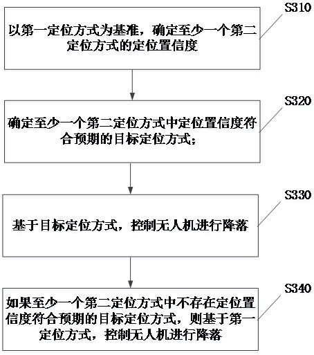
[0093] Considering that the positioning reliability of the second positioning method does not meet expectations, the embodiment of the present invention provides another drone landing method, image 3 A schematic flowchart of another drone landing method provided by an embodiment of the present invention is shown.
[0094] refer to image 3 , the UAV landing method includes:
[0095] Step S310, based on the first positioning method, determine the position reliability of at least one second positioning method;
[0096] Step S320, determining at least one target positioning method whose positioning reliability meets expectations in the second positioning method;
[0097] Step S330, based on the target positioning method, controlling the UAV to land.
[0098] Step S340, if there is no target positioning method whose position reliability meets expectations in at least one second positioning method, then control the UAV to land based on the first positioning method.
[0099] In...
no. 3 example
[0101] Figure 4 A schematic diagram of a drone landing device provided by an embodiment of the present invention is shown.
[0102] refer to Figure 4 , the UAV landing device includes: a first determination module 401, a second determination module 402 and a control module 403;
[0103] Wherein, the first determination module 401 is used to determine the location reliability of at least one second positioning method based on the first positioning method;
[0104] The second determining module 402 is configured to determine the target positioning method whose positioning reliability meets expectations in the at least one second positioning method;
[0105] The control module 403 is used for controlling the UAV to land based on the target positioning method.
[0106] In an optional implementation manner, the power consumption of the first positioning manner is greater than any one of the at least one second positioning manner, and the positioning position reliability is a p...
PUM
 Abstract
Description
Claims
Application Information
 - R&D
- Intellectual Property
- Life Sciences
- Materials
- Tech Scout
- Unparalleled Data Quality
- Higher Quality Content
- 60% Fewer Hallucinations
Browse by: Latest US Patents, China's latest patents, Technical Efficacy Thesaurus, Application Domain, Technology Topic, Popular Technical Reports.
© 2025 PatSnap. All rights reserved.Legal|Privacy policy|Modern Slavery Act Transparency Statement|Sitemap|About US| Contact US: help@patsnap.com


