
A main wire capture system and a J-type wire clip wiring device using the system

A wiring device and main wire technology, which is applied in the direction of clip connection conductor connection, etc., can solve the problems of wiring device failure to mount, wire connection failure, main wire detachment, etc., and achieve the effect of improving the capture success rate

Active Publication Date: 2021-06-04
ELECTRIC POWER RES INST OF STATE GRID ANHUI ELECTRIC POWER +1
View PDF1 Cites 0 Cited by
  • Summary
  • Abstract
  • Description
  • Claims
  • Application Information

AI Technical Summary

Problems solved by technology

[0011] In such a case, in fact, the main wire does not completely enter the main wire clamp of the J-shaped wire clamp, but the baffle plate presses the J-shaped wire clamp, which will give construction workers a sense of success in capturing the main wire. Illusion, however, the capture state of the main wire will cause the wiring device to be unable to be mounted on the main wire, and the main wire will be easily detached from the J-shaped clamp, making the wire connection work fail

Method used


Image

  • A main wire capture system and a J-type wire clip wiring device using the system
  • A main wire capture system and a J-type wire clip wiring device using the system
  • A main wire capture system and a J-type wire clip wiring device using the system

Examples


Embodiment Construction

[0071] It should be noted that, in the case of no conflict, the embodiments in the present application and the features in the embodiments can be combined with each other. The present invention will be described in detail below with reference to the accompanying drawings and examples.

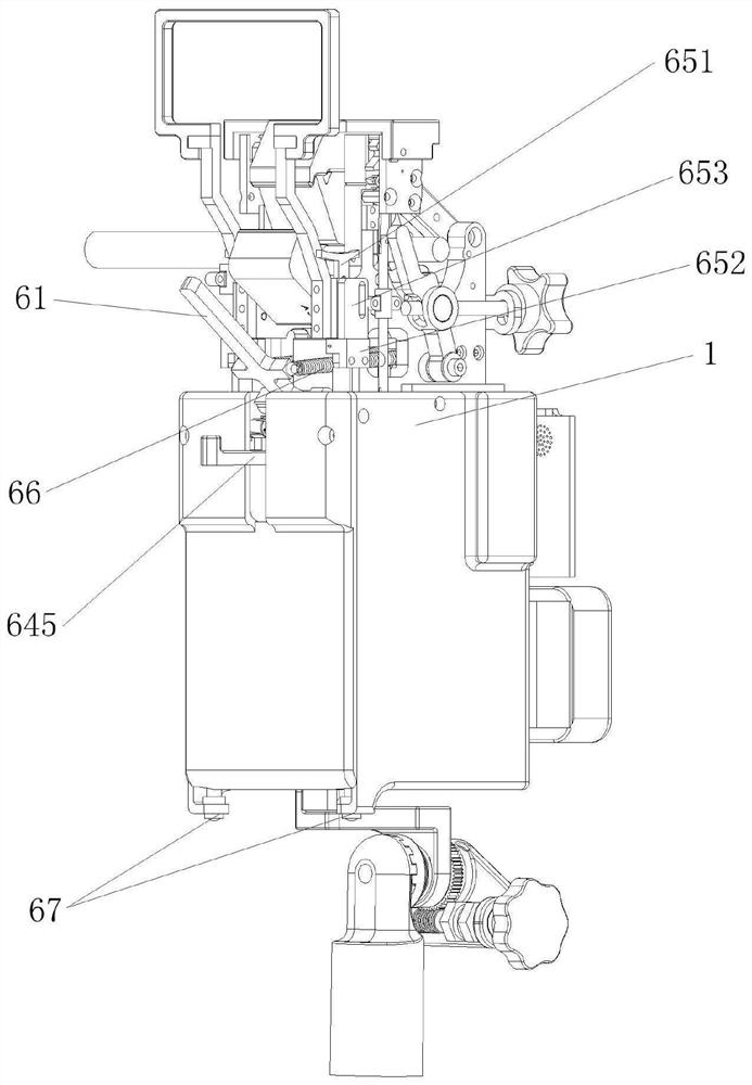
[0072] The J-shaped clamp wiring device in the present invention includes a main body 1, a clamp support structure for suspending and supporting the J-shaped clamp, a clamp fixing module for fixing the J-shaped clamp, and a clamp for clamping and fixing the branch wire 100. Branch wire clamping mechanism, and main wire capture system.

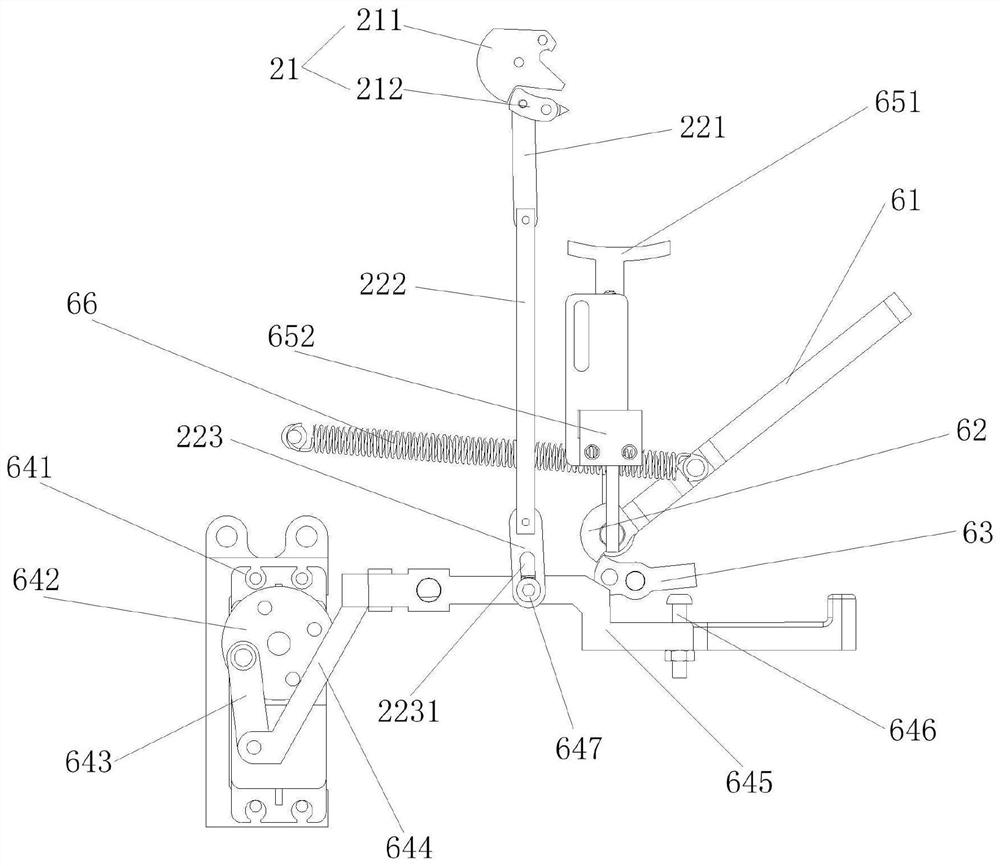
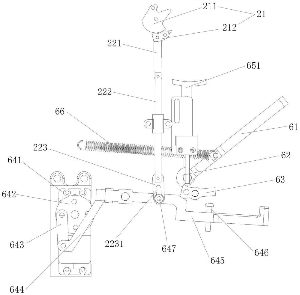
[0073] The main wire capture system includes a baffle 61, a second rotation block 62, a second rotation limiter 63, a baffle drive spring 66 for driving the baffle 61 against the J-shaped clamp, and a baffle drive spring 66 for driving The second rotation limiting block 63 returns to the initial position of the reset torsion spring, the trigger mechanism, and t...


PUM


Abstract

The invention discloses a main wire capture system and a J-shaped clamp wiring device using the system. The main wire capture system is used in the J-shaped clamp wiring device and includes a baffle for pressing the J-shaped clamp , the baffle plate position locking structure composed of the second rotation block and the second rotation limit block, the baffle plate driving spring, and the two sides of the main body arranged in the J-shaped clamp wiring device for connecting with the main wire Two trigger units, a controller, and a drive assembly that are in contact, wherein the two trigger units are electrically connected to the controller, and the controller controls the drive when both trigger units are triggered by the main lead pressing down and continue for a set time When the component moves, the driving component forms a linkage relationship with the second rotation limit block, so as to drive the position locking structure of the baffle to unlock when the driving component moves, so that the baffle can press against the J-shaped clamp. The invention provides guarantee for reliable clamping of the main wire, and can improve the success rate of capturing the main wire.

Description

technical field [0001] The invention belongs to the field of electric power operation, and in particular relates to a main wire capture system and a J-shaped clamp wiring device using the system. Background technique [0002] As a kind of power connection fittings, J-shaped clamp is used to connect two wires to form an electrical path. The two wires are generally called the main wire and the branch wire (branch wire). [0003] The J-shaped wire clamp is composed of 2 J elements with wedges and 1 bolt. The J-shaped wire clamp adopts the wedge-shaped constant contact pressure technology. The longitudinal tightening force of the bolt and the lateral action of the two J elements act on the main wire and the branch wire. The force does not interfere with each other, even if the spring washer of the bolt gradually loses its elasticity during operation, and the fastening force decreases, the contact performance will not be significantly affected, and it is less affected by the envi...

Claims


Application Information

Patent Timeline
Patent Type & Authority Patents(China)
IPC IPC(8): H01R43/027
CPCH01R43/027
Inventor 吴少雷冯玉吴凯凌松史亮李珍宝张建
Owner ELECTRIC POWER RES INST OF STATE GRID ANHUI ELECTRIC POWER
Learn More