Vehicle roll driving mechanism and design method thereof

A drive mechanism, vehicle side technology, applied in the field of vehicle roll drive mechanism and design, vehicle roll drive and control, and can solve the problems of poor handling stability, ride comfort, safety and reliability, etc.

Active Publication Date: 2020-09-22
河南坐骑科技有限公司
View PDF11 Cites 6 Cited by
  • Summary
  • Abstract
  • Description
  • Claims
  • Application Information

AI Technical Summary

Problems solved by technology

[0003] Vehicle active roll technology is usually implemented in two ways: independent body roll and vehicle body and wheel linkage roll. The former independent body roll method is usually driven by an actuator through a reducer to decelerate or directly drive the body to rotate relative to the frame. The structure is simple and the cost is low, but the handling stability, ride comfort and safety reliability of the vehicle during driving are poor; The tilt mechanism realizes the vehicle roll through the suspension movement, and the body roll, vehicle steering and wheel suspension movement affect each other. For high-end vehicles; exploring vehicle active roll driving methods, researching vehicle roll transmission and control methods, has theoretical significance and practical value for reducing the cost of active rolling vehicles and improving the performance of active rolling vehicles

Method used


Image

  • Vehicle roll driving mechanism and design method thereof
  • Vehicle roll driving mechanism and design method thereof
  • Vehicle roll driving mechanism and design method thereof

Examples


example 1

[0109] Design Example 1: given: rocker length c = 60mm, maximum swing angle β 0 =30°, crank-rocker mechanism extreme angle α 0 = 10°;

[0110] Obtained by calculation: The relative positional relationship θ of the limit position I of the rocker 10 =30.5875°, θ 30 =55.7874°, crank median angle θ 11 =73.6645°;

[0111] The length of each rod of the vehicle roll driving mechanism a=28.0425mm, b=125.5506mm, c=60mm, d=117.6760mm;

[0112] Installation angle γ=-4.2126°, rocker limit position I crank angle α 1 =-104.2520°, rocker limit position II crank angle α 2 =85.7480°; roll function Variable value range: α=-104.2520°~85.7480°.

example 2

[0113] Design Example 2: given: rocker length c = 120mm, maximum swing angle β 0 =45°, crank-rocker mechanism extreme angle α 0 = 20°;

[0114] Obtained by calculation: The relative positional relationship θ of the limit position I of the rocker 10 =35.0719°, θ 30 =48.2192°, median crank angle θ 11 =80.1141°;

[0115] The length of each rod of the vehicle roll driving mechanism a=75.8697mm, b=231.6011mm, c=120mm, d=207.4093mm;

[0116] Installation angle γ=3.2192°, rocker limit position I crank angle α 1 =-115.1861°, rocker limit position II crank angle α 2 =84.8139°; roll function Variable value range: α=-115.1861°~84.8139°.

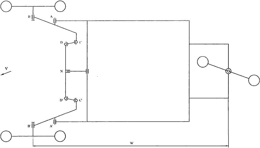
[0117] Figure 8 The design schematic diagram of the reverse drive vehicle roll drive mechanism is shown. In the above design method of the vehicle roll drive mechanism, the roll function is realized through the reverse transmission of β and α in the swing angle function β=f(α). roll angle The steering of the vehicle changes accordingly, a...

example 3

[0145] Design Example 3: given: rocker length c = 100mm, maximum swing angle β 0 =30°, crank-rocker mechanism extreme angle α 0 = 15°;

[0146] Obtained by calculation: The relative positional relationship θ of the limit position I of the rocker 10 =34.4069°, θ 30 =65.1522°, median crank angle θ 12 =131.6859°;

[0147] The length of each rod of the vehicle roll driving mechanism a=42.7407mm, b=203.3285mm, c=100mm, d=174.5132mm;

[0148] Installation angle γ=5.1522°, rocker limit position I crank angle α 1 =97.2790°, rocker limit position II crank angle α 2 = -67.7210°; roll function Variable value range: α=97.2790°~-67.7210°.


PUM


Abstract

The invention relates to the technical field of vehicle chassis, and discloses a vehicle roll driving mechanism and a design method thereof. The vehicle roll driving mechanism includes a vehicle body,a balance rod, a crank, a connecting rod, a rocker, a positioning rod, swing arms, pull rods, wheels and shock absorbers, the crank, the connecting rod, the rocker and the positioning rod are sequentially and rotationally connected to form a crank rocker mechanism in the same relative motion plane, the crank and the connecting rod are overlapped and collinear to form a rocker limit position I, the crank and the connecting rod are stretched and collinear to form a rocker limit position II, and two limit positions of the rocker correspond to left and right limit roll of a vehicle. The inventionprovides the design method of the length, the roll function and the roll direction of each rod of the vehicle roll driving mechanism. Meanwhile, the invention provides two active roll three-wheeled vehicles applying the vehicle roll driving mechanism, so that the vehicle body actively tilts by a certain angle to resist centrifugal force or roll force when the vehicle passes through a corner or passes through an inclined road surface, and the stable driving posture of the vehicle is kept.

Description

technical field [0001] The invention relates to a vehicle roll driving mechanism and a design method, belonging to the technical field of vehicle chassis, in particular to the technical field of vehicle roll driving and control. Background technique [0002] The active roll control system improves the handling stability, smoothness, traffic speed and safety of the vehicle when turning by controlling the degree of inclination of the vehicle to the inner side of the turn. When crossing an inclined road, it automatically tilts at a certain angle to generate a balance moment to resist the centrifugal force or rollover force on the vehicle, so as to maintain a stable driving posture of the vehicle. [0003] Vehicle active roll technology is usually implemented in two ways: independent body roll and vehicle body and wheel linkage roll. The former independent body roll method is usually driven by an actuator through a reducer to decelerate or directly drive the body to rotate relat...

Claims


Application Information

Patent Timeline
Patent Type & Authority Applications(China)
IPC IPC(8): B60G17/00B60G21/055B60G13/00
CPCB60G17/00B60G21/055B60G13/00
Inventor 王亚魏文军李海涛
Owner 河南坐骑科技有限公司
Why Eureka
Try Eureka