rectification device for vehicle

A technology of a fairing device and a vehicle, which is applied in the directions of vehicle components, body, body stability, etc., can solve the problems of vehicle handling stability and riding comfort without considering, and achieve the effect of stabilizing the driving posture and reducing air resistance.

Inactive Publication Date: 2017-06-27
TOYOTA JIDOSHA KK
View PDF16 Cites 0 Cited by
  • Summary
  • Abstract
  • Description
  • Claims
  • Application Information

AI Technical Summary

Problems solved by technology

[0010] However, in the above-mentioned structure, although the deterioration of the air resistance of the vehicle is suppressed by the inclined surface and the tire deflector, the handling stability and ride comfort of the vehicle are not considered.
Therefore, in the above structure, there is room for improvement in this point

Method used


Image

  • rectification device for vehicle
  • rectification device for vehicle
  • rectification device for vehicle

Examples


no. 1 approach

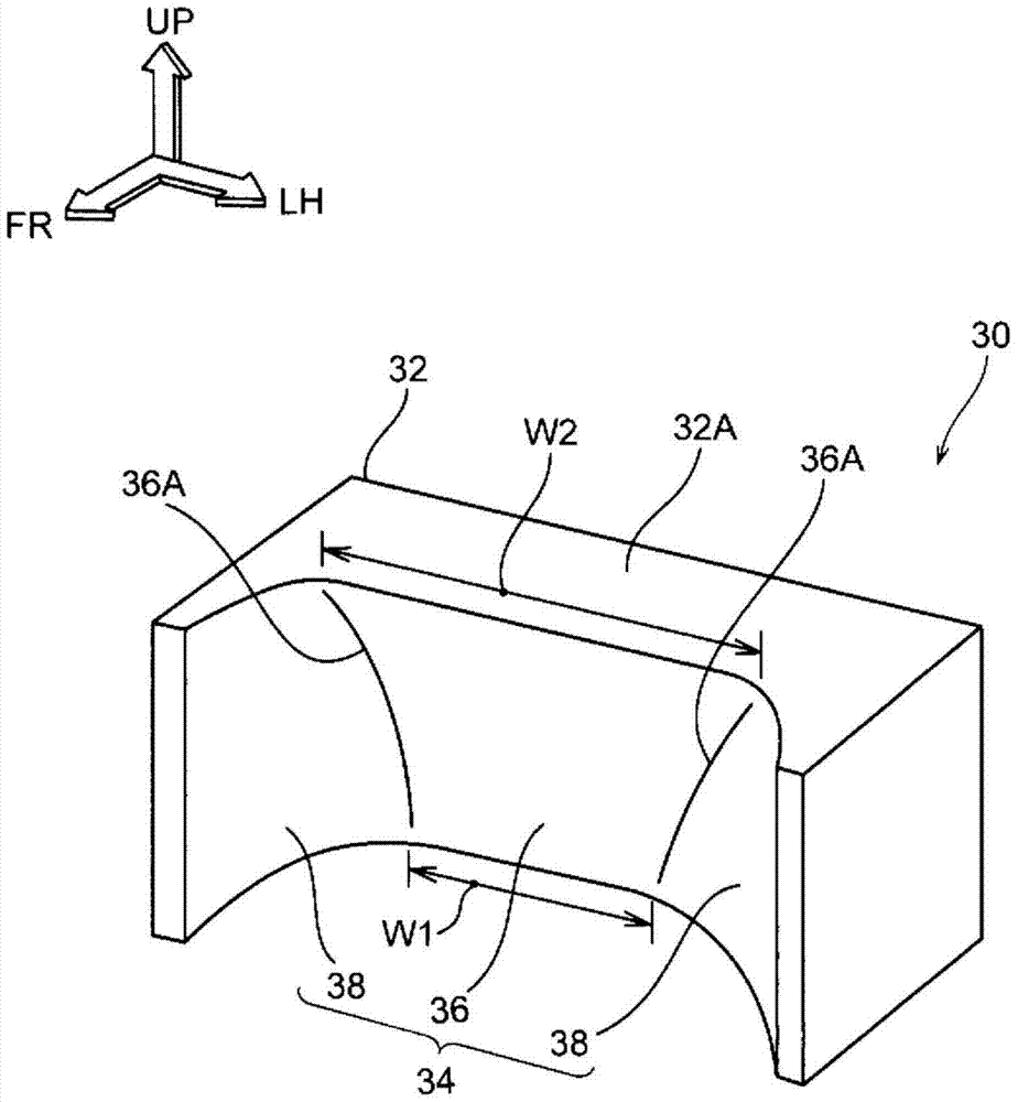
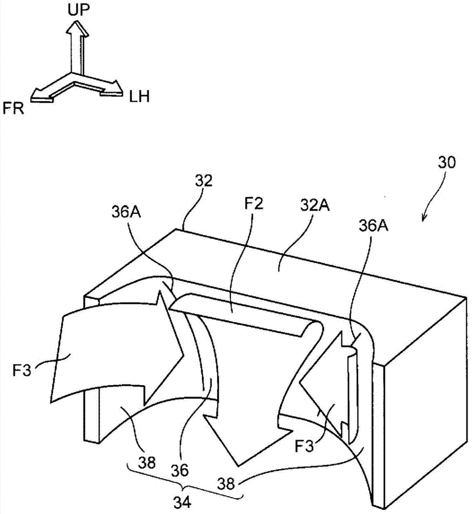
[0048] use Figures 1 to 4B , the wheel drag cover 30 as the vehicle fairing device according to the first embodiment will be described. In addition, arrow FR appropriately shown in the figure indicates the front of the vehicle, arrow LH indicates the left side of the vehicle (one side in the vehicle width direction), and arrow UP indicates the upper side of the vehicle.

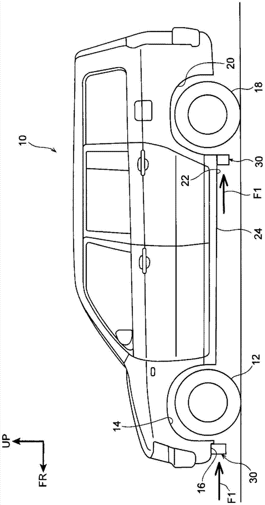
[0049] like figure 2 As shown, the wheel drag cover 30 is applied to the lower portion of the vehicle (automobile) 10 . At the front of the vehicle 10, a pair of front wheels 12 (at the figure 2 In FIG. 2 , only the front wheel 12 provided on the left side of the vehicle is shown, and a front fender bushing 14 is arranged on the outside of the front wheel 12 in the radial direction. The front fender liner 14 is formed in a substantially arc-shaped plate shape that opens downward of the vehicle in side view, and covers the upper portion of the front wheel 12 from the upper side of the vehicle. Also, alt...

no. 2 approach

[0068] Below, use Figure 5 to Figure 7 , the wheel drag cover 50 according to the second embodiment will be described. In addition, in the second embodiment, except for the shape of the wheel drag reducing cover 50 , all other structures are the same as those of the first embodiment.

[0069] In the wheel drag cover 50, the wheel drag cover 30 of the first embodiment is formed in a pair and integrally. Specifically, in the wheel cowl 50 , a pair of wheel cowls 30 are arranged symmetrically in the vehicle front-rear direction, and these wheel cowls 30 are joined together.

[0070] Accordingly, the main body portion 52 of the wheel cowl 50 is formed into a columnar shape with a substantially H-shaped cross section, and is disposed on the vehicle front side of the front wheel 12 and the rear wheel 18 . In addition, a front fairing portion 34 is formed at the front portion of the wheel cowl 50, and the front fairing portion 34 is configured to include a front inclined surface 3...


PUM


Abstract

In the front fairing portion (34) formed at the front portion of the main body portion (32) of the wheel cowl (30), the front inclined surface (36) is inclined toward the rear side of the vehicle as it goes toward the lower side of the vehicle when viewed from the side. , the front side surface (38) extends toward the vehicle front side from both ends (36A) of the front inclined surface (36) in the vehicle width direction. And, because the running wind (F3) that touches the front side (38) flows toward the front inclined surface (36) side and flows out from the front rectifying portion (34) toward the lower side of the vehicle together with the running wind (F2), the running wind (F2 , F3) the flow rate increases. This prevents the traveling wind (F2, F3) from hitting the front wheels (12) and the like, thereby reducing the air resistance of the vehicle. In addition, by increasing the flow velocity of the traveling wind ( F2 , F3 ) and causing buoyancy to act on the vehicle to cancel the buoyancy and gravity, the steering stability of the vehicle can be improved. Furthermore, since the vertical movement of the vehicle is suppressed by the buoyancy, the ride comfort of the vehicle can be improved.

Description

technical field [0001] The invention relates to a vehicle rectifying device. Background technique [0002] The tire deflector (wheel drag cowl) described in the following Patent Document 1 is arranged on the outer side of the engine underguard in the vehicle width direction. Specifically, an inclined surface is formed at an outer end portion of the engine floor guard in the vehicle width direction, and tire deflectors are arranged on the vehicle rear side and the vehicle width direction outer side of the inclined surface. In addition, when the vehicle is running, since the running wind flowing through the vehicle width direction outer side of the engine underguard hits the inclined surface and the tire deflector, all of the running wind is prevented from hitting the tire deflector. Case. As a result, deterioration of the Cd value (air resistance coefficient) of the vehicle is suppressed. [0003] prior art literature [0004] patent documents [0005] Patent Document 1:...

Claims


Application Information

Patent Timeline
Patent Type & Authority Patents(China)
IPC IPC(8): B62D37/02B62D25/20B62D35/02
CPCB62D35/02Y02T10/88Y02T10/82B62D37/02B62D25/20
Inventor 内山荣一小林邦啓浅野一秀宫下胜己古谷祐人
Owner TOYOTA JIDOSHA KK
Why Eureka
Try Eureka