Follow-flying-type differential lock structure

A differential lock and flywheel technology, applied in the differential transmission, belt/chain/gear, mechanical equipment, etc., can solve the problem that the turning action of the differential lock is difficult to achieve on the opposite side of the in-situ tank turning action.

Pending Publication Date: 2020-09-22
安冬
View PDF9 Cites 0 Cited by
  • Summary
  • Abstract
  • Description
  • Claims
  • Application Information

AI Technical Summary

Problems solved by technology

[0005] The purpose of the present invention is to provide a fly-by differential lock device to solve the problem that ...

Method used


Image

  • Follow-flying-type differential lock structure
  • Follow-flying-type differential lock structure
  • Follow-flying-type differential lock structure

Examples


Embodiment Construction

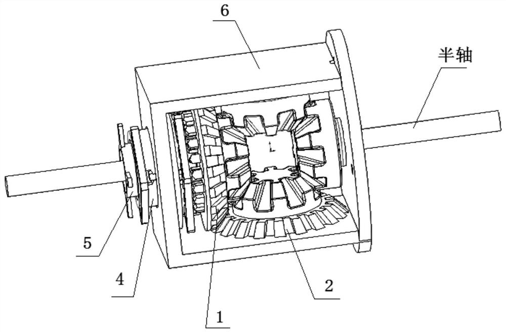
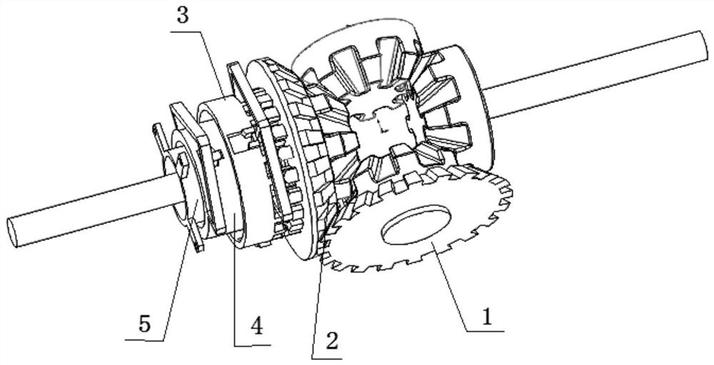
[0038] Such as figure 1 and 2 As shown, a fly-on differential lock structure includes a flywheel 1, a central driven planetary gear 2, a housing fault-tolerant sliding sleeve 3, a housing fault-tolerant sliding sleeve 4, a housing 5 and a housing 6;

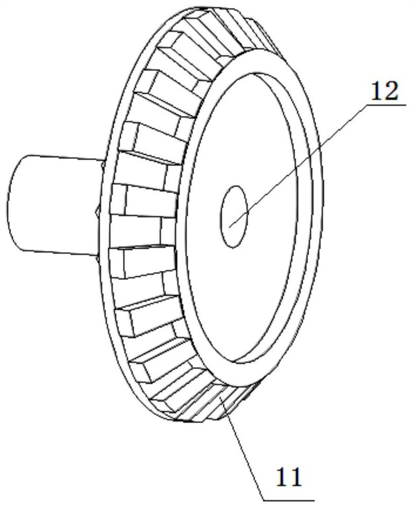
[0039] Such as image 3 and 4 As shown, the front edge of the flywheel 1 is provided with a flywheel bevel tooth 11, the middle is provided with a light through hole 12, the outer ring of the back side of the flywheel 1 is provided with an outer wheel back tooth 13, and the inner ring is provided with an inner wheel back tooth 14;

[0040] Such as Figure 5 As shown, the housing fault-tolerant sliding sleeve 3 is socketed with the casing fault-tolerant sliding sleeve 4, and is toothed with the outer wheel of the flywheel 1. The casing fault-tolerant sliding sleeve 4 is socketed on the casing 5, and the casing The fault-tolerant sliding sleeve 3 is sleeved on the housing 6 .

[0041] Such as Figure 6 As shown, the central d...


PUM


Abstract

The invention discloses a follow-flying-type differential lock structure. The follow-flying-type differential lock structure comprises a follow-flying wheel, a centrally-driven planetary gear, a shellfault-tolerant sliding sleeve, a covering shell fault-tolerant sliding sleeve, a covering shell and a shell. A follow-flying-type differential lock provided by the invention can achieve the locking action, is used for vehicle liberating, and can also achieve the vehicle in-situ tank turning action and the reverse in-situ tank turning action.

Description

technical field [0001] The invention belongs to the technical field of automobile differential locks, and relates to a fly-on-the-fly differential lock structure. Background technique [0002] The differential is mainly used to balance the speed difference between the inner and outer wheels when the vehicle is turning, so that the vehicle can turn smoothly without consuming too much energy, and it will not cause too much wear to the wheels of the vehicle during the turning process. It is precisely because of the differential principle of the differential and the effect of equal torque that when the car is running, the wheels often fall into mud pits or fields, causing a certain wheel to slip or even hang in the air, so that the vehicle is trapped and unable to extricate itself. [0003] In order to solve the asynchronous phenomenon of the wheels on both sides of the vehicle during operation, a differential lock is installed in the differential of the vehicle. A differential...

Claims


Application Information

Patent Timeline
IPC IPC(8): F16H48/20F16H48/40F16H48/08
CPCF16H48/20F16H48/40F16H48/08F16H2048/208
Inventor 安冬
Owner 安冬
Why Eureka
Try Eureka