Flow guiding assembly and oil fume treatment device

A technology of oil fume treatment and deflectors, which is applied in the field of range hoods, can solve the problems of consumers such as cleaning troubles and runny noses, and achieve the effect of improving oil pollution and reducing cleaning frequency and difficulty

Pending Publication Date: 2020-09-22
FOSHAN SHUNDE MIDEA WASHING APPLIANCES MFG CO LTD
View PDF0 Cites 0 Cited by
  • Summary
  • Abstract
  • Description
  • Claims
  • Application Information

AI Technical Summary

Problems solved by technology

[0002] In the related technology, the condensed oil on the oil net of the range hood is sucked along the flange of the oil net and sucked into the bellows under the action of the wind force during the start-up time of the fan, but after the fan stops, the condensed oil flows along the outside of the flange under the action of gravity. The edge flows down, flows to the upper edge of the smoke shield glass, and accumulates on it, and then the oil flows down the glass, forming a runny nose, which brings great trouble to consumers' cleaning

Method used


Image

  • Flow guiding assembly and oil fume treatment device
  • Flow guiding assembly and oil fume treatment device
  • Flow guiding assembly and oil fume treatment device

Examples


Embodiment 1

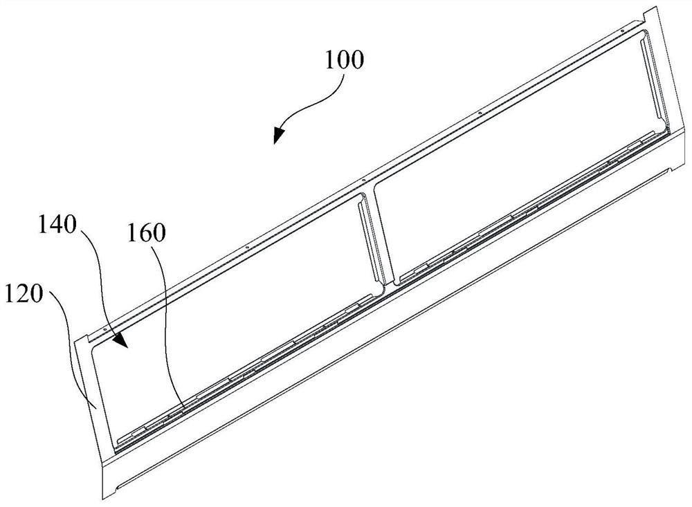
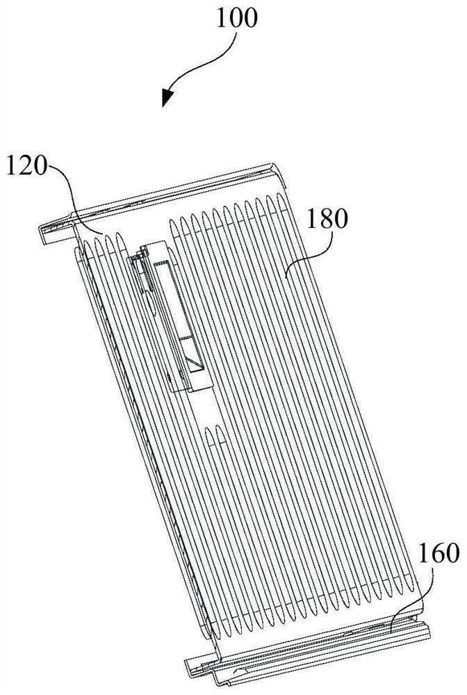
[0065] Such as figure 1 with figure 2 As shown, an embodiment of the present invention provides a deflector assembly 100 for an oil fume treatment device 200 , including: a frame body 120 , a grille 180 and a first deflector 160 , and the air inlet 140 is located in the frame body 120 Above, the grille 180 is connected to the frame body 120, and the grille 180 covers the air inlet 140; The first deflector 160 is located between the bottom surface of the grid 180 and the frame body 120, the first deflector 160 is located below the grid 180, and the first deflector 160 can control the flow of water flowing down from the grid 180. Liquid diversion.

[0066] In this embodiment, the air guide assembly 100 includes a frame body 120 , a grille 180 and a first air guide member 160 , the frame body 120 is provided with an air inlet 140 , and the grille 180 is embedded in the air inlet 140 of the frame body 120 , the grille 180 can guide the air flowing through the air inlet 140, th...

Embodiment 2

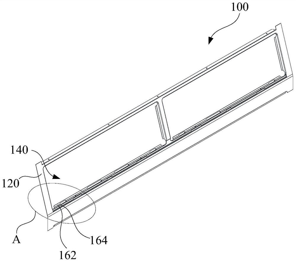
[0085] Such as figure 1 As shown, an embodiment of the present invention provides a deflector assembly 100 for an oil fume treatment device 200 , including: a frame body 120 , a grille 180 and a first deflector 160 , and the air inlet 140 is located in the frame body 120 Above, the grille 180 is connected to the frame body 120, and the grille 180 covers the air inlet 140; The first deflector 160 is located between the bottom surface of the grid 180 and the frame body 120, the first deflector 160 is located below the grid 180, and the first deflector 160 can control the flow of water flowing down from the grid 180. Liquid diversion.

[0086] The first deflector 160 also includes: a connected first plate 162 and a second plate 164, a positioning protrusion 166, an angle is provided between the first plate 162 and the second plate 164, and the angle Greater than or equal to 90° and less than or equal to 180°, the first plate 162 is connected to the frame body 120 , and the firs...

Embodiment 3

[0100] Such as image 3 As shown, an embodiment of the present invention provides a cooking fume treatment device 200, including: a body 210; a smoke guide channel 220, the smoke guide channel 220 is set in the body 210; a smoke baffle 230, the smoke baffle 230 is set in On the body 210; as the flow guide assembly 100 in the first and / or second embodiment above, the flow guide assembly 100 is connected to the smoke baffle 230, and the flow guide assembly 100 is configured to guide the fluid to the smoke guide channel 220 Inside, wherein, the top surface of the smoke baffle 230 is higher than the first deflector 160 in the deflector assembly 100 along the direction of gravity. Therefore, it has all the beneficial effects of the above-mentioned embodiment 1 and embodiment 2, which will not be repeated here.

[0101] In this embodiment, the oil fume treatment device 200 includes a body 210 , a smoke guide channel 220 , a smoke baffle 230 and a flow guide assembly 100 . The smok...


PUM


Abstract

The invention provides a flow guiding assembly and an oil fume treatment device. The flow guiding assembly is used for the oil fume treatment device. The flow guiding assembly comprises a frame, a grating and a first flow guiding component, wherein an air inlet is formed in the frame; the grating is connected with the frame and arranged at the air inlet; and the first flow guiding component is arranged on the frame, located between the bottom surface of the grating and the frame and suitable for guiding liquid flowing from the grating. According to the flow guiding assembly and the oil fume treatment device provided by the invention, gas flowing through the grating can enter a fume guide channel of the oil fume treatment device, and liquid condensed on the grating can be further guided; and accordingly, by arranging the flow guiding assembly on the oil fume treatment device, the greasy dirt status of the oil fume treatment device is improved, and the cleaning frequency and difficulty of consumers are reduced.

Description

technical field [0001] The invention belongs to the technical field of range hoods, and in particular relates to a flow guide assembly and a cooking fume treatment device. Background technique [0002] In the related technology, the condensed oil on the oil net of the range hood is sucked along the flange of the oil net and sucked into the bellows under the action of the wind force during the start-up time of the fan, but after the fan stops, the condensed oil flows along the outside of the flange under the action of gravity. The edge flows down, flows to the upper edge of the smoke-shielding glass, and accumulates on it, and then the oil flows down along the glass, forming a runny nose, which brings great trouble to consumers' cleaning. Contents of the invention [0003] The present invention aims to solve one of the technical problems existing in the prior art or related art. [0004] To this end, the first aspect of the present invention proposes a flow guide assembly....

Claims


Application Information

Patent Timeline
Patent Type & Authority Applications(China)
IPC IPC(8): F24C15/20
CPCF24C15/20F24C15/2042
Inventor 王建宇彭小康杨飞刘星郭峰蒋济武温群杨余悦泳
Owner FOSHAN SHUNDE MIDEA WASHING APPLIANCES MFG CO LTD
Why Eureka
Try Eureka