Guide plate, gas-liquid separator, compressor assembly and air conditioner
A deflector and liquid deflector technology, which is applied in the field of compressors, can solve the problems of poor liquid separation capacity and increase in the amount of liquid in the exhaust, so as to reduce the amount of liquid in the suction, reduce the amount of liquid in the exhaust, and reduce the amount of liquid in the exhaust. The effect of airflow noise
- Summary
- Abstract
- Description
- Claims
- Application Information
AI Technical Summary
Problems solved by technology
Method used
Image
Examples
Embodiment 1
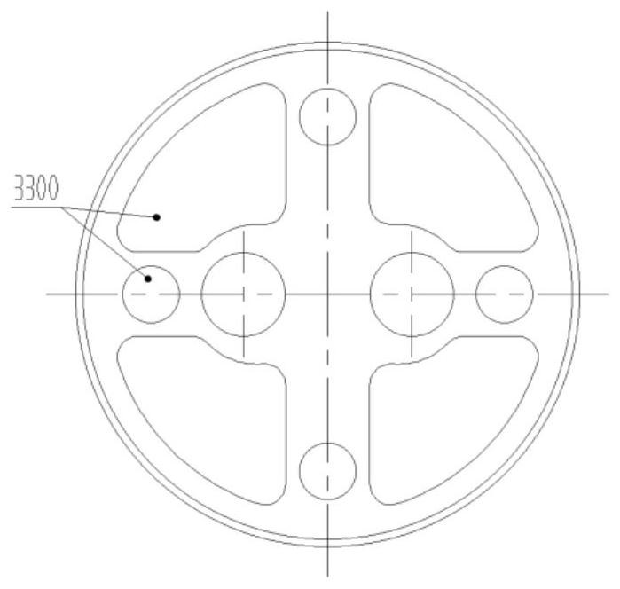
[0053] combined with Figures 3a-3c , 4, the liquid flow falls along the inner wall of the cylinder body 7 in the liquid distributor, gathers in the first liquid collecting tank 4 of the liquid collecting part 3100, and then passes through the guiding effect of a plurality of liquid guiding holes 3102 and the liquid guiding plate 3103, Converge the liquid flow at the central axis position of the lower cylinder 8 of the liquid separator, and the liquid falls into the second liquid collecting tank 4.1. Due to the impact of the liquid flow and the evaporation of the gaseous refrigerant, the air flow is forced to move upward along the inner wall of the lower cylinder 8, and the air flow The liquid flow space formed by a plurality of liquid guide plates rises and collects into the air collection chamber 3202 of the air collection part 3200, and then is discharged into the cylinder of the liquid separator through the exhaust hole 3203 under the action of the air collection plate 3201...
Embodiment 2
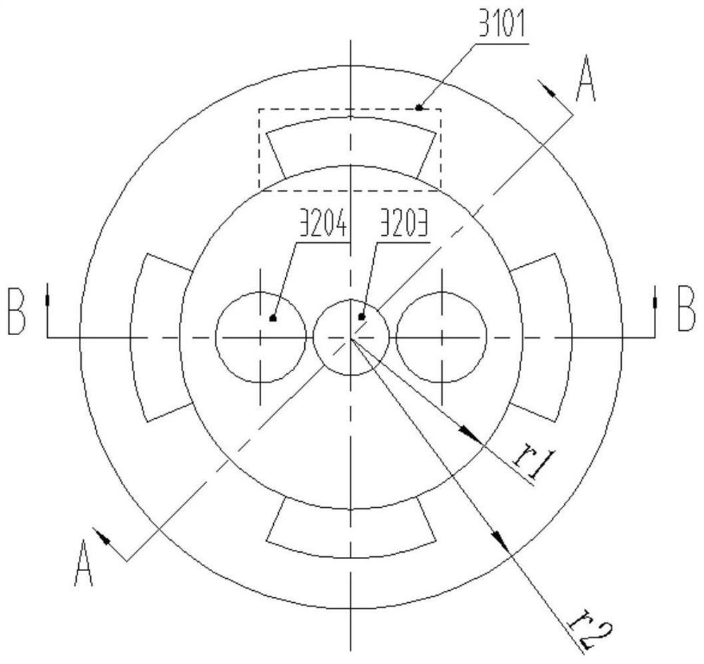
[0055] combined with Figures 5a-5b , 6, the guide direction of the multiple liquid guide plates 3103 of the guide plate 3 points to the inner wall of the lower cylinder body 8 of the liquid distributor, and guides the liquid flow to drop to the second liquid collecting tank 4.1 along the inner wall. Due to the impact of the liquid flow The action and the evaporation of the gaseous refrigerant force the airflow to move upward along the central axis of the lower cylinder 8 , and the airflow enters the exhaust pipe 6 after being discharged through the exhaust hole 3203 .
[0056] further, Figure 7a-7b , 8, the shape of the exhaust hole 3203 is a combination of circular and rectangular holes, and can also be a circular hole, a special-shaped hole, etc., and its flow area is affected by the displacement of the compressor. If the displacement is large, the exhaust hole will be large.
[0057] The invention can meet the demand of the compressor to reduce the amount of liquid carri...
Embodiment 4
[0081] combined with Figure 9 , 10 As shown, in the single exhaust straight tube liquid separator, the diameter of the exhaust hole 3203 of the deflector 3 is 1.5 times or more than the diameter of the exhaust pipe 6, and the liquid flow in the middle cylinder 7 of the gas-liquid separator passes through After deflector guides the flow, it flows downward along the wall of the exhaust straight pipe in the lower cylinder 8, and the airflow is discharged through the exhaust hole 3203, and merges with the airflow in the middle cylinder to enter the exhaust pipe 6.
[0082] further, Figures 11a-11b 12. The shape of the exhaust hole 3203 of the deflector 3 is a plurality of oval holes, and the installation hole 3204 is directly connected with the exhaust pipe.
[0083] In some embodiments, the installation hole 3204 is a circular hole, the exhaust hole 3203 is a non-circular hole, and there are a plurality of non-circular holes, and the plurality of non-circular holes are along ...
PUM
 Abstract
Description
Claims
Application Information
 - R&D
- Intellectual Property
- Life Sciences
- Materials
- Tech Scout
- Unparalleled Data Quality
- Higher Quality Content
- 60% Fewer Hallucinations
Browse by: Latest US Patents, China's latest patents, Technical Efficacy Thesaurus, Application Domain, Technology Topic, Popular Technical Reports.
© 2025 PatSnap. All rights reserved.Legal|Privacy policy|Modern Slavery Act Transparency Statement|Sitemap|About US| Contact US: help@patsnap.com


