
Liquid accumulator and compressor assembly

A technology of liquid receiver and liquid separator, which is applied in the field of compressors, can solve the problems of poor liquid separation ability of liquid separator and increase of liquid carried by exhaust of liquid separator, so as to reduce the amount of liquid carried by exhaust and reduce Fluid volume, the effect of avoiding liquid shock

Active Publication Date: 2022-03-25
GREE ELECTRIC APPLIANCES INC OF ZHUHAI
View PDF4 Cites 0 Cited by
  • Summary
  • Abstract
  • Description
  • Claims
  • Application Information

AI Technical Summary

Problems solved by technology

[0005] Therefore, the technical problem to be solved by the present invention is to overcome the defect that the gas-liquid hedging of the liquid reservoir in the prior art leads to poor liquid separation ability of the liquid separator, which leads to an increase in the amount of liquid carried by the exhaust of the liquid separator, thereby providing a accumulator and compressor assembly

Method used


Image

  • Liquid accumulator and compressor assembly
  • Liquid accumulator and compressor assembly
  • Liquid accumulator and compressor assembly

Examples


Embodiment 1

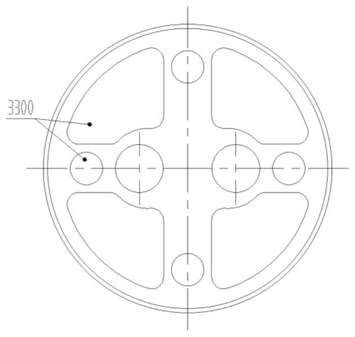
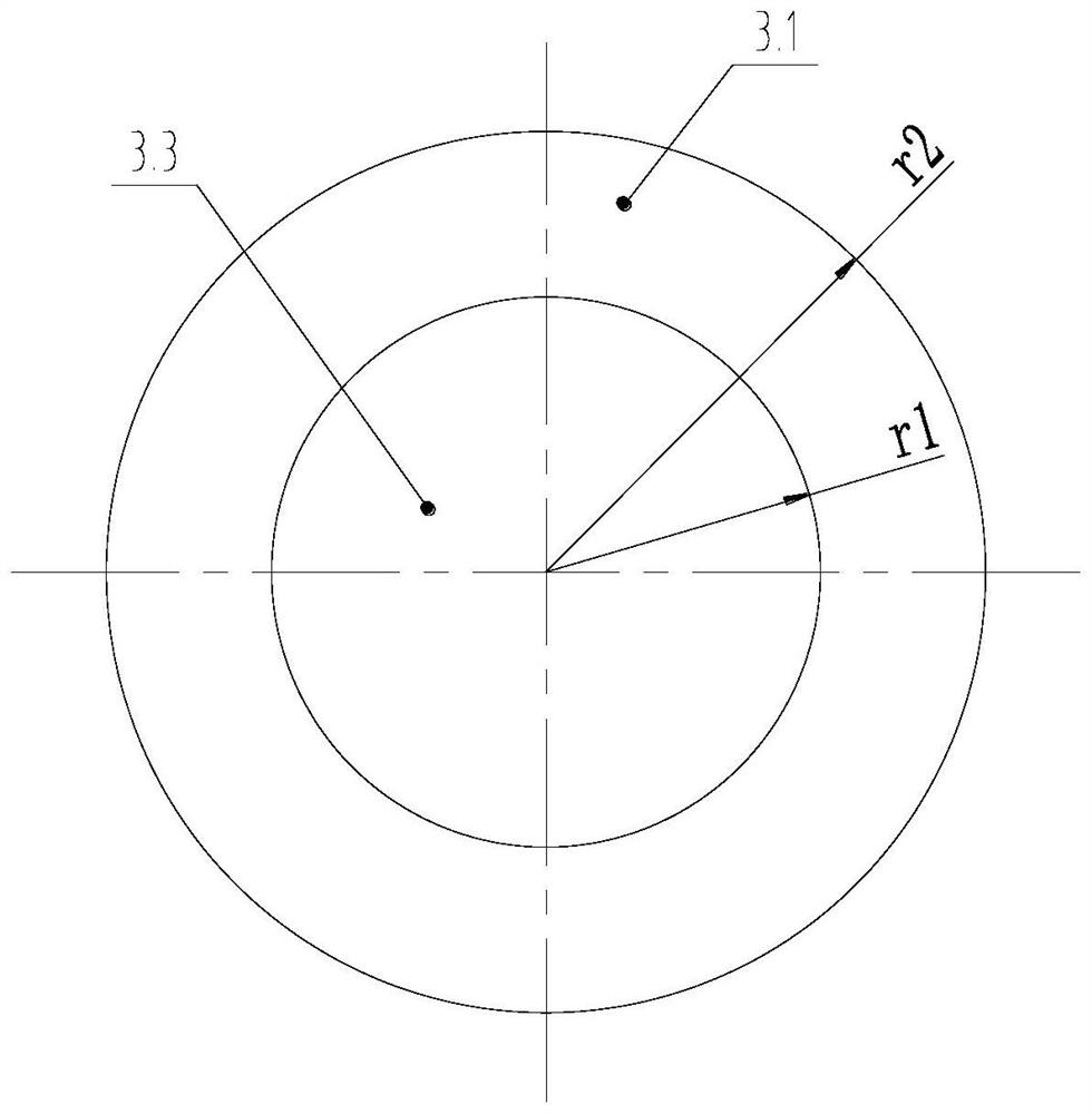
[0053] Example 1, such as Figure 3a-5 As shown, in some embodiments, the first partition 3.1 is located above the second partition 3.2, at this time, an air flow channel is formed between the first partition 3.1 and the second partition 3.2, At the same time, the flow channel 3.5 is formed as a liquid flow channel, so that the liquid can flow through the flow channel 3.5 to the bottom of the second partition 3.2, and the gas can pass through the first partition 3.1 and the second partition 3.2 to flow above the first partition 3.1. This is the preferred structural form of Embodiment 1 of the present invention, that is, the first partition is located above the second partition, and the gap between the first partition and the second partition is used for upward gas flow, and the second partition The opened circulation channels are used to circulate liquid downwards, thereby forming separate air flow channels and liquid flow channels, preventing gas-liquid hedging and improving...

Embodiment 2

[0057] Example 2, such as Figure 6a-Figure 9 As shown, in some embodiments, the first partition 3.1 is located above the second partition 3.2, at this time, the first part of the circumferential segment of the first partition 3.1 and the second partition 3.2 A first liquid flow channel is formed between the first part of the circumferential section of the first partition, and an airflow channel is formed between the second part of the circumferential section of the first partition 3.1 and the second part of the circumferential section of the second partition 3.2, At the same time, the flow channel 3.5 is formed as a second liquid flow channel, so that the liquid can flow to the second separator 3.3 through the first liquid flow channel, and flow to the second separator 3.2 through the flow channel 3.5 Below, the gas can flow to the first partition 3.1 through the gas flow channel between the second partial circumferential section of the first partition 3.1 and the second part...

Embodiment 3

[0064] Example 3, such as Figures 10a-13b , in some embodiments, the first partition 3.1 is located below the second partition 3.2, at this time a liquid flow channel is formed between the first partition 3.1 and the second partition 3.2, and at the same time The circulation channel 3.5 is formed as an air flow channel, so that the liquid can flow to the bottom of the second separator 3.2 through the gap between the first separator 3.1 and the second separator 3.2, and the gas can pass through the second separator 3.2. The flow channel 3.5 flows to the top of the first partition 3.1. This is the preferred structural form of Embodiment 3 of the present invention, that is, the first dividing plate is located below the second dividing plate, and the gap between the first dividing plate and the second dividing plate is used for direct downward flow of liquid, and the second dividing plate The circulation channel opened on the partition is used to circulate gas upwards, thereby f...


PUM


Abstract

The invention provides a liquid accumulator and a compressor assembly.The liquid accumulator comprises a liquid separator barrel, a first partition plate, a second partition plate and an exhaust pipe, and the first partition plate and the second partition plate are both arranged in the liquid separator barrel; the exhaust pipe extends into the liquid separator barrel from the lower part of the liquid separator barrel, and the upper end of the exhaust pipe is positioned above the first partition plate and the second partition plate; the radial periphery of the first partition plate is connected with the inner circumferential wall of the liquid separator barrel, the second partition plate is provided with an installation hole and a circulation channel, the second partition plate is arranged on the exhaust pipe in a sleeving mode through the installation hole, and the first partition plate and the second partition plate are arranged at intervals in the axial direction and are located in the projection plane of the axial end face. The first partition covers part of the surface of the second partition or the second partition covers part of the surface of the first partition. According to the invention, a gas path and a liquid path are effectively separated, the problem of poor liquid storage capacity of the liquid separator caused by gas-liquid hedging is solved, the exhaust liquid carrying amount of the liquid separator is greatly reduced, and the risk of liquid impact of a compressor is reduced.

Description

technical field [0001] The invention relates to the technical field of compressors, in particular to a liquid accumulator and a compressor assembly. Background technique [0002] As an important part of the compressor, the liquid accumulator is mainly used to prevent the occurrence of liquid hammer. When the compressor is running in an unsteady state, the incompletely evaporated liquid refrigerant in the system will enter the compressor, causing a series of reliability problems in the pump body. At this stage, the gas-liquid separation part in the liquid separator is a filter screen bracket, which is located near the suction port of the liquid separator, which can reduce the amount of liquid carried by the exhaust of the liquid separator, that is, the amount of liquid carried by the suction on the side of the pump body. [0003] It has been observed through experiments that the structure of the partition plate in the existing liquid separator and the structure of the upper ...

Claims


Application Information

Patent Timeline
IPC IPC(8): F25B43/00
CPCF25B43/006F25B2500/28
Inventor 王明宗邓丽颖徐嘉杨欧翔余蔚
Owner GREE ELECTRIC APPLIANCES INC OF ZHUHAI
Learn More